Valve
To add
a new valve, click the button  of Components toolbar
or use the corresponding item of "Insert
- Component" menu. Please note that the new component
is added to the project tree after the currently selected element. Therefore,
to add a new component after an existing one, select it in the project
tree or in the graphic window and add the new component. If you need to
add a new component to the beginning of a branch, select the branch in
the project tree and add the new component.
of Components toolbar
or use the corresponding item of "Insert
- Component" menu. Please note that the new component
is added to the project tree after the currently selected element. Therefore,
to add a new component after an existing one, select it in the project
tree or in the graphic window and add the new component. If you need to
add a new component to the beginning of a branch, select the branch in
the project tree and add the new component.
The
valve element is used to model the hydraulic resistance caused by the
change of velocity and, possibly, the direction of flow in valves of different
types, as well as for the selection and calculation of the characteristics
of control valves.
After
adding valve, its characteristics will be displayed in the Object Properties
Window:
|
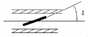
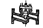
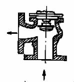
Knife
gate valve |
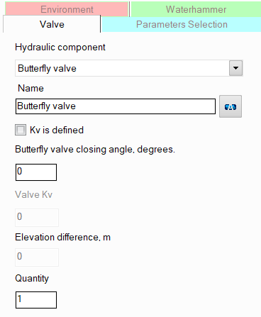
It
is necessary to specify the relative rod height of the valve,
defined as the ratio h/D (see the figure on the left). At h/D = 1,
the valve is fully open, at h/D = 0, it is fully closed.
If
the purpose of your calculation is to determine the required valve
rod position to control some flow parameter in a pipeline (pressure,
flow rate, etc.), see more details about such calculations here
|
|
Gate valve |
|
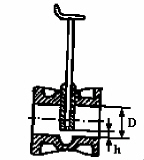
Valve
with a symmetric narrowing of the flow passage (for example, pinch
valve) |
|
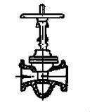
Butterfly
valve |
It
is necessary to specify the valve closure angle (i.e., the angle
of rotation of the valve's flap in relation to the pipe axis).
An angle of 0° corresponds to a fully open shutter, 90° -
fully closed.
If the purpose of
your calculation is to determine the required valve
closure angle to control some
flow parameter in a pipeline (pressure, flow rate, etc.), see
more details about such calculations here |
|
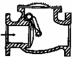
Swing check valve |
For
these types of valves, additional parameters for calculation are
not required. |
|
Lift check valve |
|
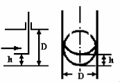
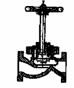
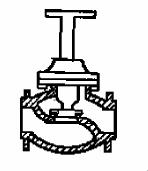
Globe
valve |
|
Forged
globe valve |
|
Globe
valve with dividing rods under a 45° angle |
|
Angle valve |
|
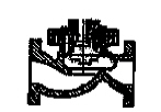
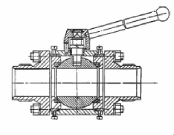
Ball valve |
|
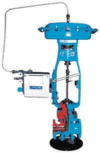
Control valve |
The control valve refers to a flow control valve. For this type of valve, it is
necessary to specify the fluid flow rate that it is to control.
Control
valves must not be installed as the first or last elements in
a branch, or immediately before or after tees.
Please
note that when using the "Control valve" element, it
is assumed that the valve flow coefficient Kv is unknown, and
it is necessary to determine what it should be so that the valve
maintains the required flow value. Therefore, if you have already
selected a control valve (i.e., its flow coefficient is known),
model it not as a "Control valve", but as any other
type of valve (no matter which) with a known Kv value - see below
for more information.
For
more details on the hydraulic calculation task formalization for
pipelines with control valves and their boundary conditions, see here |
Please note that when specifying valves with a relative
rod height equal to zero, or butterfly valves with a valve closure
angle of 90°, or any type of valve with a
specified flow coefficient Kv equal to 0 (for more details on this coefficient,
see below), the flow in this branch is considered blocked,
which is taken into account when calculating the pipeline.
name -
by default, the name of any piping component coincides with its type,
but if necessary, the name can be changed in this field. When changing
the hydraulic component type (when selecting different types of valves),
its name will also change, but only if it has not been previously
changed to another manually. Specify the name that you would like
to see for this element in reports with calculation results. To display
the name of a pipeline element on the diagram, click the corresponding
button to the right of its name;
quantity -
this parameter is used in cases when it is necessary to simulate and
calculate the resistance and heat losses of several valves of the
same types (gate/ball valves, etc.), without specifying each of them
separately. To do this, enter the number of such valves in this field,
and at the calculation, the hydraulic resistances and heat losses
on this valve will be multiplied by the specified value. Of course,
not all valves will be displayed on the graphical diagram (only one
of them will be displayed), but they will be taken into account in
the calculation. However, it is important
to note that this method of setting not always gives a good accuracy
of calculation, since it does not take into account that a change
in pressure and temperature after the next piping component may entail
a change in the density and viscosity of the fluid (which is especially
crucial for gases and gas-liquid mixtures), and, consequently, a change
in the pressure drop on subsequent elements. This method can be used
for a quick rough estimate and mainly for liquids, the properties
of which don't change (for instance, at a constant temperature) or
change slightly along the pipeline. For a more accurate calculation,
you should specify all components sequentially in the exact order
they appear (even if there are repeating ones among them);
valve Kv - the Kv coefficient of
the valve is a value numerically equal to the flow rate in m3/h of
a fluid with a density of 1000 kg/m3, at which the pressure loss on
the valve is equal 0.1 MPa. If the
value of this coefficient is known for the valve, it can be taken
into account in the calculation. To do this, enable the "Kv is
defined" option and enter the Kv coefficient in the corresponding
field. In this case, the calculation of the valve resistance will
be carried out not according to the standard reference data for the
selected type of valve, but on the basis of the entered Kv value,
knowing which it is easy to determine the pressure drop on the valve
at any flow rates for fluids with any density (the type of valve does
not play any role when specifying Kv). The Kv assignment is convenient
to use in modeling:
various
other types of valves that are not included in the program among
the available types of valves (if the value of the Kv coefficient
for this valve can be found in the passport or reference data);
control
valves that have already been selected in advance (and for which
their Kv value in the controlling state is already known).
For standard types of valves,
it is not necessary to specify the Kv value, since this will not lead
to a significant increase in the calculation accuracy.
Also in practice, along with the
Kv coefficient for valves in reference literature and passport characteristics,
you can find a similar value - the Cv coefficient, defined as the volume
of water at 60°F (in US gallons) that will flow through a valve per minute
with a pressure drop of 1 psi across the valve. Knowing the Cv coefficient,
you can easily calculate the value of the Kv coefficient as: Kv = 0.864*Cv.
If you need
to model any other types of valve that
are not included in the list of those available in the program, they can
be specified as a:
component
with known loss coefficient - values or formulas
for calculating local losses coefficients of valves of various
types can be found in the reference data books;
valve with a specified value of the Kv flow coefficient - the Kv/Cv values for valves can be found
in its passport data and in the relevant reference literature.
If the purpose of your calculation
is to calculate the parameters of control valves (to control pressure,
flow rate, flow temperature) and determine the required value of its flow
capacity coefficient Kv (to maintain the required
flow rate, pressure, etc.), see
more details about such calculations here.
Please note that from a hydraulic
point of view, the valve is considered as a "point" (or "concentrated")
resistance that has no length. That is, friction losses and possible hydrostatic
pressure drop on the valve are not taken into account in the calculation.
Therefore, if it is necessary to take into account the dimensions of such
a valve in the calculation to calculate and account for the friction losses,
heat losses and hydrostatic pressure drop that occur on it, they can be
modeled separately as a piece of pipe with the corresponding length, or
the length of the valve can be added to the lengths of the pipes adjacent
to the valve. However, this only makes sense in cases where:
the
valve has really large size that cannot be neglected;
the valve is located in a vertical or inclined
plane relative to the vertical - in this case, it is important to
take into account the hydrostatic pressure drop that occurs on it;
the valve is located in a closed loop (so
that the piping model looks correctly, without gaps).
In other cases, friction losses on
the valves (and therefore its
length) are usually neglected.