Bend/elbow
To add
a new bend, click the button  of Components toolbar
or use the corresponding item of "Insert
- Component" menu. Please note that the new component
is added to the project tree after the currently selected element. Therefore,
to add a new component after an existing one, select it in the project
tree or in the graphic window and add the new component. If you need to
add a new component to the beginning of a branch, select the branch in
the project tree and add the new component.
of Components toolbar
or use the corresponding item of "Insert
- Component" menu. Please note that the new component
is added to the project tree after the currently selected element. Therefore,
to add a new component after an existing one, select it in the project
tree or in the graphic window and add the new component. If you need to
add a new component to the beginning of a branch, select the branch in
the project tree and add the new component.
The bend element is used to model
the hydraulic resistances of the bend or elbow:
the
local resistance caused by a smooth flow turn in bend;
the
friction losses, since the bend is in fact a curved section of the
pipe with a length equal to the length of the bend arc at the center
of its cross-section (the length of the bend arc will be displayed
in the calculation results), which has a friction;
the
hydrostatic losses - only in case the bend "turns" in a
vertical or inclined plane.
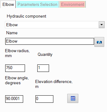
After
adding a bend, its characteristics will be displayed in the Object Properties
Window:
|
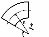
Elbow |
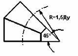
It
is necessary to specify the radius R and the angle φ of the elbow.
The default angle is 90° and the radius is:
R=1.5·DN at DN <500, R=DN at DN >=500 |
|
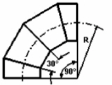
90° mitre bend |
For this type of bend the angle
is fixed (90°), the radius R must be entered.
The default is:
R=1.5·DN at DN <500, R=DN at DN >=500 |
|
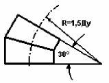
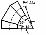
30°
mitre bend |
For this type of bend, both the angle (30°)
and the radius R=1.5DN are fixed.
There is no need to specify them. |
|
45°
mitre bend
|
For
this type of bend, both the angle (45°) and the radius R=1.5DN are fixed.
There is no need to specify them. |
|
60°
mitre bend
|
For
this type of bend, both the angle (60°) and the radius R=1.5DN are fixed.
There is no need to specify them. |
name -
by default, the name of any piping component coincides with its type,
but if necessary, the name can be changed in this field. When changing
the hydraulic component type (when selecting different types of bends),
its name will also change, but only if it has not been previously
changed to another manually. Specify the name that you would like
to see for this element in reports with calculation results. To display
the name of a pipeline element on the diagram, click the corresponding
button to the right of its name;
quantity -
this parameter is used in cases when it is necessary to simulate and
calculate the resistance (and heat losses) of several identical bends/elbows
in a branch, without specifying each of them separately. To do this,
enter the number of such bends in this field, and at the calculation,
the hydraulic resistances and heat losses on this bend will be multiplied
by the specified value. Of course, not all bends will be displayed
on the graphical diagram (only one of them will be displayed), but
they will be taken into account in the calculation. However,
it is important to note that this method of setting not always gives
a good accuracy of calculation, since it does not take into account
that a change in pressure and temperature after the next piping component
may entail a change in the density and viscosity of the fluid (which
is especially crucial for gases and gas-liquid mixtures), and, consequently,
a change in the pressure drop on subsequent elements. This method
can be used for a quick rough estimate and mainly for liquids, the
properties of which don't change (for instance, at a constant temperature)
or change slightly along the pipeline. For a more accurate calculation,
you should specify all components sequentially in the exact order
they appear (even if there are repeating ones among them).
elevation
difference - the elevation difference of a bend is the
vertical distance between the center of its outlet and inlet cross-sections
(a positive difference means that
the component's exit point is located higher than the entry point,
a negative difference means the opposite).
Please note that it is not necessary
to set the bend angle and the elevation difference manually - these parameters
can be automatically calculated based on the specified directions of the
pipes before and after the bend and the bend size (radius) by clicking
the "Recalc by graphics" button (in the form of a blue "calculator")
for this bend in the Object Properties Window or by enabling the "Recalculate
elevations and angles on graphic before every analysis" option in the program
settings (in the second case, before each calculation,
the program will automatically recalculate the elevation differences on
all pipeline elements, bend angles, etc. and store/correct them in the
input data). To display the "Recalc by graphics" button, do
not forget to enable the "Scaled graphic view" and "Show
all components" options in the pipeline graphic view options (on
the View Options
toolbar); in addition, the "Precise graphic representation of
scaled view" option must be enabled in the program settings.
Since
from a hydraulic point of view a bend is considered as a "dimensional"
resistance (i.e., having a length), this must be taken into account when
specifying the pipes adjacent to it, indicating their actual lengths
as the dimensions of these pipes (for more information, see here).
It
is not recommended to install bends as the first and last elements in
a branch, since the orientation of the bend in space is determined by
the direction of the pipes located before and after it. Therefore, if
there are no pipes before and/or after the bend, it will be impossible
to accurately determine its orientation in space, and the bend may be
displayed incorrectly on the diagram (however, of course, this will not
affect the correctness of the calculation).