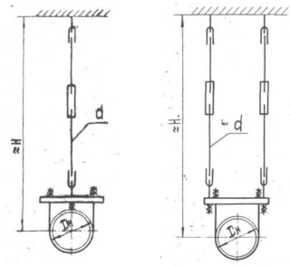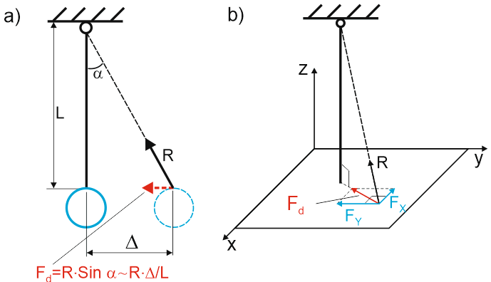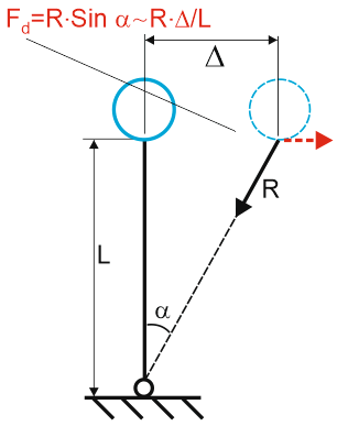
Vertical rigid rod hangers restrict downward movement while allowing upward displacement. When a hanger moves from vertical alignment, horizontal force components develop that tend to restore the original vertical position.


Rigid stands resist compression forces. Model rigid stands using negative length values.

Rigid rod hangers are modeled using one vertical linear unilateral restraint and two simulated horizontal restraints. See "Custom Restraints"

Property |
Description |
Name |
Element identifier. When checked, displays in 3D view. |
Weight |
Weight of the support component attached to the pipe. This weight is applied at the attachment node. When building structure load capacity is specified, the calculated load includes both piping weight and support weight. When support load capacity is specified, either omit support weight or increase allowable load by the support weight value. |
Rod/Stand length, H |
Rod length used for calculating simulated restraint reactions. See "Custom Restraints" Zero length ignores additional forces from vertical displacement. Positive length models rigid rod hangers. Negative length models rigid stands. |
Check allowable loads |
START-PROF automatically verifies that analysis results remain within specified load limits. Warnings display when limits are exceeded. |
Loads in local axes |
When unchecked, allowable loads reference global coordinate axes; when checked, they reference local axes of the connected element |
FX, FY, FZ |
Allowable load values for X, Y, and Z axes |
To insert this element, select the target node and use: Insert > Insert Restraint > Rigid Rod Hanger
or click the  toolbar icon.
To view element properties:
Double-click the element in the 3D view
Select the
element and click the  toolbar icon