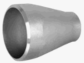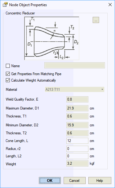


Reducers can only be placed on straight pipe segments between elements with different diameters. The reducer node is located at the smaller diameter end.
The reducer weight is modeled as a uniform load. The pipe weight covered by the reducer is removed. Insulation and fluid weights are averaged from the two connected pipes. Snow, ice, wind, and user-defined uniform loads are also averaged from adjacent pipes.
ASME Code Considerations:
START-PROF does not perform wall thickness checks for reducers under ASME codes. For Russian codes, wall thickness checks are performed for all reducer types.

Property |
Description |
Name |
Element identifier. When checked, displays in 3D view |
Material |
Material from the materials database |
Automatic Weight Calculation |
When selected, calculates reducer weight as truncated cone volume with linear wall thickness variation |
Weight |
Reducer weight excluding insulation and content. Uses standard value without overload factor. Content and insulation weights with overload factors are automatically calculated from adjacent pipes. |
Wall Thickness at Dmax, t1 |
Nominal wall thickness at maximum diameter |
Wall Thickness at Dmin, t2 |
Nominal wall thickness at minimum diameter |
Mill Tolerance |
Manufacturing tolerance for wall thickness. More... |
Corrosion and Wear Allowance |
Corrosion and wear allowance (service tolerance) for wall thickness. More... |
Cone Length, Lc |
Length of conical reducer section |
Full Length, L |
Total reducer element length |
Cone Angle, α |
Slope angle of conical section. k=2 for concentric reducers
|
Longitudinal Weld Joint Efficiency Factor, E |
Longitudinal weld joint efficiency factor. More... |
Manufacturing Technology |
For ASME B31.1, ASME B31.3, DL/T 5366-2014, seamless pipe uses Wl=1.0. Electric-welded pipe uses Wl from database. More... For GOST 32388-2013, pipe properties are taken from different materials databases based on pipe type (seamless/welded). |
Stress Correlation Along Two Axes, r |
Based on ISO 14692 section 7.10
|
Qualified Stress, qs |
If blank, value is taken from material database Based on ISO 14692 section 7.8
|
Internal Protective Layer Thickness |
|
External Protective Layer Thickness |
|
To insert a reducer, select the desired node and use: Insert > Insert Reducer > Insert Concentric Reducer
To view element properties:
Double-click the element in the 3D view
Select the
element and click the  toolbar icon