Read about START-PROF pipe stress analysis software
The Elements module analyzes L, Z, and U-shaped pipe loops, eliminating outdated nomograms. Analysis types include:
Above-ground horizontal loops
Above-ground vertical loops
Buried horizontal loops
Start-Elements provides approximate expansion joint modeling with linearized soil. START-PROF uses exact non-linear soil models for greater accuracy.
Use Start-Elements for preliminary analysis only. Final verification requires START-PROF.
During analysis, START-PROF automatically generates loop models with resting supports at safe intervals calculated per support spacing guidelines. Pipe wall thickness is verified using wall thickness analysis.
Horizontal and vertical loop dimensions differ significantly. In horizontal planes, thermal and weight bending stresses act in perpendicular planes. In vertical planes, they combine in the same plane, reducing allowable stress capacity. Traditional nomograms often ignore plane orientation.
Bend flexibility in loop angles is optional. Disable "reduced bend stiffness" to compare with nomograms that assume rigid bends. Bend wall thickness equals pipe wall thickness.
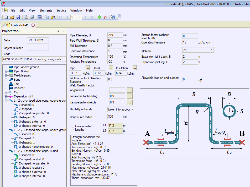
Two analysis modes are available: design validation and verification. Design validation calculates maximum allowable shoulder length meeting stability and stress requirements (check "compensated length"). Verification computes maximum stress for specified dimensions (uncheck "compensated length"). Both determine anchor loads, maximum stress, transverse displacement, and allowable stress.
Bend stress checks follow SNIP 2.05.06-85 load requirements.
Copy input data using  and paste into other Start-Elements
analyses using
  .
.

Property |
Description |
Pipe diameter, D |
External pipe diameter |
Pipe wall thickness, S |
Nominal wall thickness |
Mill tolerance |
Manufacturing tolerance. More... |
Corrosion allowance |
Corrosion and wear allowance. More... |
Bend radius |
Radius for all loop bends. Affects reduced bend stiffness calculation. |
Casing outside diameter, Dc |
External insulation casing diameter. Set to 0 if no insulation. |
Casing thickness, SC |
Insulation casing thickness |
Depth, Z |
Distance from soil surface to pipe axis |
Ambient temperature |
Pipe metal temperature during system assembly |
Operation pressure, P |
Operating pressure for all standards except SNIP 2.05.06-85. More... |
Operation pressure, Pwork |
Operating pressure for SNIP 2.05.06-85. More... |
Pipe weight |
Uniform weight of piping and attached equipment. More... |
Insulation weight |
Uniform insulation weight. More... |
Product weight |
Uniform product weight. More... |
Weld pressure quality factor |
|
Weld bending quality factor |
|
Insulation type |
Armopenobeton, polymer, polyurethane, other. For polyurethane, casing diameter DC and thickness SC auto-populate from database. Manual entry required for other types. |
Backfill soil code |
Trench soil number from soil database. |
Base soil code |
Base soil number from soil database. |
Resting support friction factor |
Friction factor range: 0.05–0.4. Set to 0 to ignore friction (no friction restraints). |
Steel grade |
Pipe material from materials database. |
Flexibility of bends |
Include bend flexibility in loop angles. Disable to compare with rigid-bend nomograms. Including flexibility increases compensated lengths. |
Cushion presence |
Include damping cushions. Note: cushions don't always increase allowable axial movement and may reduce function in buried pipelines. |
Pre-stretch factor, k |
Pre-stretching reduces maximum pipe stress. k=0: no pre-stretch. k=0.5: pre-stretch equals half the thermal displacement. k=0.1: 10% of thermal displacement. Range: 0–1.0. |
Loop back, B and leg, H |
Input loop back and leg dimensions before analysis. Compensated lengths are calculated. Multiple B/H combinations exist for a given compensated length; select structurally sound values. |
Allowable load on end support |
Maximum allowable anchor load. Loop dimensions ensure loads don't exceed this value. Set to 0 to disable anchor load check (dimensions based on stability only). |
Analysis Output
Analysis results include:
Property |
Description |
Maximum stress |
Maximum equivalent stress in piping elements |
Allowable stress |
Allowable stress per RD 10-400-01 1.5[O], and design resistance R2 for SNIP 2.05.06-85
|
Thermal stretch |
Maximum thermal expansion (long shoulder) with one anchor removed. Used for pre-stretch determination. |
Maximum transverse displacement |
Maximum node displacement (bend ends). Used for selecting damping cushion thickness based on maximum deformation. |
Lguide |
Shoulder length experiencing transverse displacement. Determines minimum distance from loop to guiding support.
|
Loads on A and B anchors |
|
Axial force |
Force along pipe axis |
Transverse force |
Force perpendicular to pipe axis (shear) |
Bending moment |
Bending moment |
Error "Expansion joint is not self-compensated" (e.g., for L-shaped loop with short leg L1 and long leg L) indicates the loop fails strength requirements even at L=L1, and will fail at L1<L.
Loops