

|
PASS/NOZZLE-FEM 3.5. Program Manual | |
Practice has shown that in a number of cases calculation at the 1st and 2nd mesh levels has the following disadvantages:
| - | most users do not perform verification calculations at high mesh levels (4th, 5th); |
| - | for tasks where the difference between stresses at the 1st and 5th levels is insignificant, taking into account the mesh coefficient Km = 1.3, there is a significant increase in stresses and as a result of acceptance of no optimal design solutions (see the first point); |
| - | insufficient grid density at low mesh levels may lead to a miss of the peak stress value and as a result acceptance of incorrect design solutions (see the first point). |
 |
 |
| a. | b. |
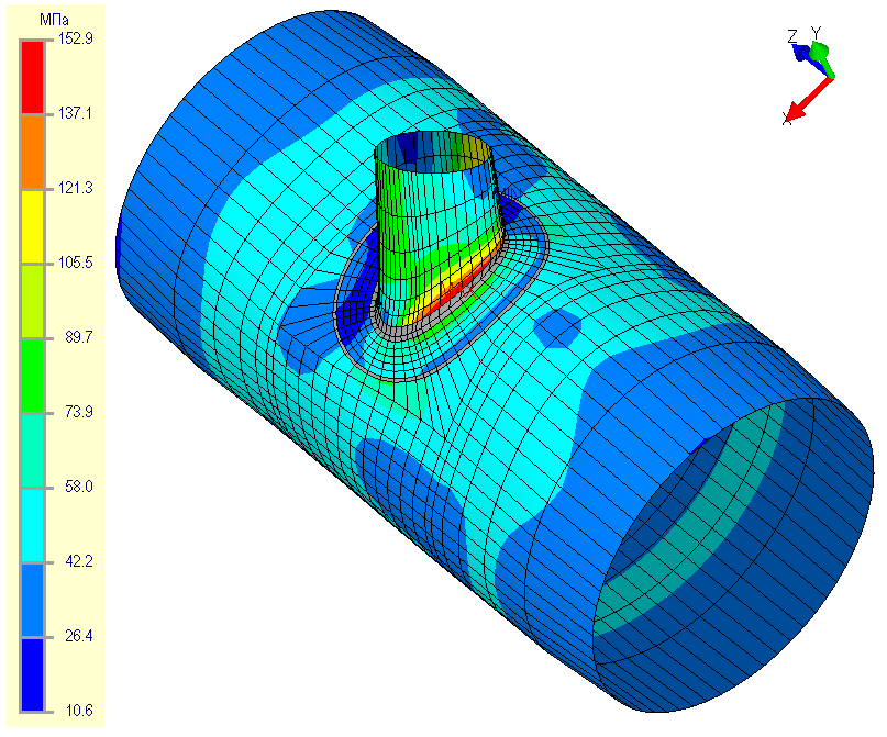
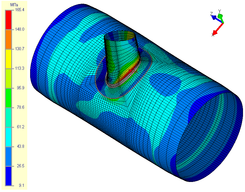
| Fig. 5.18. Equivalent membrane stresses at 1th (a) and 5th (b) mesh levels | |
The above is an example where a small stress difference at different mesh levels leads to different conclusions about strength. The maximum equivalent membrane stresses at the 1st level is 152.9 MPa (fig. 5.18a), and at the 5th level they is 165.4 MPa (fig. 5.18b). The value of the allowable stress in this example is 131 MPa. Taking into account the mesh coefficients, we obtain the following calculated stresses and conclusions about the strength conditions:
| σ1ml max = 1.30·152.9 = 198.77 > 1.5[σ] = 1.5·131.0 = 196.5 | (failure for 1th level), |
| σ1ml max = 1.05·165.4 = 173.67 < 1.5[σ] = 1.5·131.0 = 196.5 | (success for 5th level). |
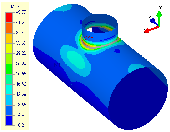
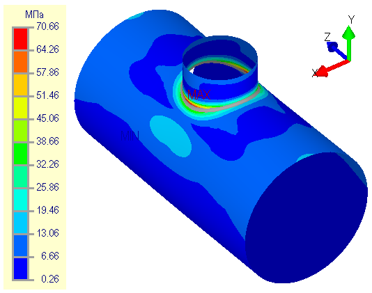
At the second example on fig. 5.19 (nozzle under by action axial force of 100 kN), when the grid has an insufficient "density" in the weld region, shows that the peak stresses can not be determined even at the 5th mesh level (see the same example below). Here the total stresses (membrane + bending) on the outer surface at the 1st level amounted to 45.75 MPa (fig. 5.19a), taking into account the mesh coefficient $K_m=1.30$, the calculated stresses will be equal to 59.48 MPa. Total stress at the 5th level amounted to 70.66 MPa (fig. 5.19b), and taking into account the mesh coefficient $K_m=1.05$, the calculated stress will be equal to 74.19 MPa. Thus maximum value of the stresses at the 1st level is much less than the value at the 5th level. It will be shown below that the maximum peak values are not obtained at the 5th level here.
 |
 |
| a. | b. |
| Fig. 5.19. Total (membrane and bending) stresses at 1th (a) and 5th (b) mesh levels | |
The latter circumstance strongly influences the accuracy of determining the allowable loads (section "Calculation of allowable loads") and stress intensification factors (section "Calculation of stress intensification factors"). Below is the calculation of the stress intensification factors from the axial force for the 1st level and the 5th mesh levels, respectively:
$$ \begin{array}{l} i_{a,1th} = \frac{1.35}{2}\frac{\sigma_{PEAK}}{\sigma_{NOM}} = \frac{1.35 \cdot 59.48}{2 \cdot 6.24} = 6.434, \\ i_{a,5th} = \frac{1.35}{2}\frac{\sigma_{PEAK}}{\sigma_{NOM}} = \frac{1.35 \cdot 74.19}{2 \cdot 6.24} = 8.025. \end{array} $$
To reduce effect of the such problems, programm version 2.5 implements the procedure of stress extrapolation at weld toe (stress concentration area). The stress extrapolation can be enabled/disabled tab sheet "Project properties".
Procedure stress extrapolation is implemented by Hot Spot Stress (HSS) method [26-29]. The method is that the calculated stress value at the stress evaluation line (fig. 5.20), where the "peak" stresses are determined, is calculated by linear extrapolation at the points $t_1$ and $t_2$ (Linear Surface Extrapolation - LSE), whose choice depends on the shell thickness $s$. This approach makes the stress defination process at the concentrators stable and allows to obtain the close results for different mesh levels of the FE-models (increases the result convergence).
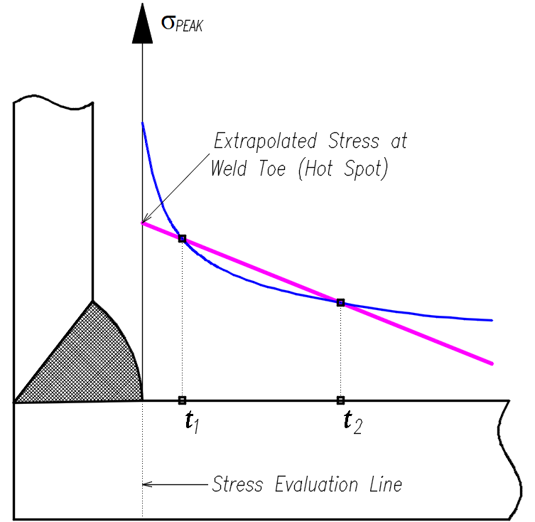 |
| Fig. 5.20. Hot Spot Stress (HSS) method |
For the correct stress extrapolation it is necessary to specify a certain step of the regular grid near the stress concentrators (weld toes) depending on the shell thickness (fig. 5.21). The such grid density will allow to "catch" the peak stress already at the 1st mesh level.
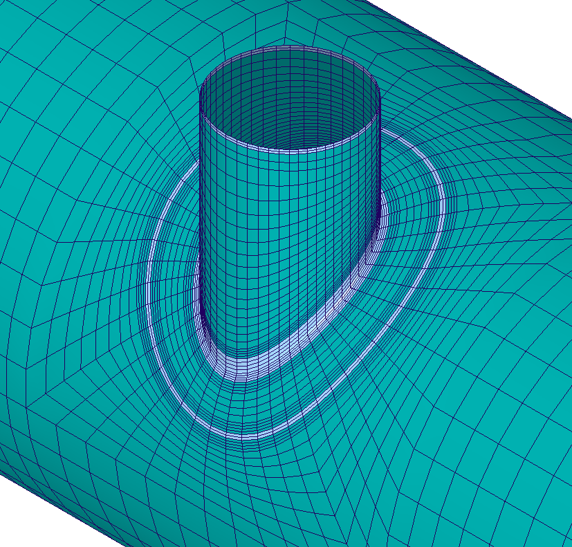 |
| Fig. 5.21. Mesh alignment and refinement at the weld toe |
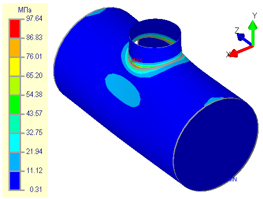
Consider second example (fig. 5.22) with enabled stress extrapolation. The total stresses (membrane + bending) on the outer surface at the 1st level amounted to 97.64 MPa (fig. 5.22a), taking into account the mesh coefficient $K_m=1.05$ (in the extrapolation mode), the calculated stresses will be equal to 102.52 MPa. The total stress at the 5th level were 96.90 MPa (fig. 5.22b), and taking into account the breakdown coefficient $K_m=1.00$ (in extrapolation mode), the calculated stresses will be equal to 96.90 MPa. It follows that the 1st and 5th mesh levels give "close" results, but significantly exceed the results without stress extrapolation.
 |
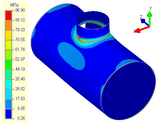 |
| a. | b. |
| Fig. 5.22. Total (membrane and bending) stresses at 1th (a) and 5th (b) mesh levels with stress extrapolation | |
Let's evaluate stress intensification factors (SIF) from axial force with stress extrapolation at the 1th and 5th mesh level accordingly:
$$ \begin{array}{ll} i_{a,1th} = \frac{1.35}{2}\frac{\sigma_{PEAK}}{\sigma_{NOM}} = \frac{1.35 \cdot 102.52}{2 \cdot 6.24} & = 11.089, \\ i_{a,5th} = \frac{1.35}{2}\frac{\sigma_{PEAK}}{\sigma_{NOM}} = \frac{1.35 \cdot 96.90}{2 \cdot 6.24} & = 10.482. \end{array} $$
The programm NozzlePRO for this example showed a similar result (fig. 5.23). The maximum stresses were obtained equal to 108.03 MPa. Hence, the stress intensification factor (SIF) from axial force will be as follows:
$$ \begin{array}{l} i_{a} = \frac{1.35}{2}\frac{\sigma_{PEAK}}{\sigma_{NOM}} = \frac{1.35 \cdot 108.03}{2 \cdot 6.496} = 11.225. \end{array} $$
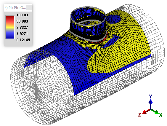 |
| Fig. 5.23. The maximum stress $P_l+P_b+Q$ received in NozzlePRO |
Thus, using the procedure of stress extrapolation, the the mesh coefficient values were refined. The new values are given in the table 5.2.
| Table 5.2. Mesh coefficient | |||||
| Mesh level | 1 | 2 | 3 | 4 | 5 |
| Mesh coefficient, Km | 1.050 | 1.038 | 1.025 | 1.012 | 1.000 |
PASS/NOZZLE-FEM 3.5. Program Manual
Copyright © 2017-2026, PASS Team