

|
PASS/NOZZLE-FEM 3.5. Program Manual | |
The stress concentration factor (SCF) is defined as follows:
| $$ SCF = \frac{K_m \sigma_{MAX}}{\sigma_{NOM}} $$ | (5.12) |
| where | $\sigma_{MAX}$ | - | maximum secondary stress (secondary membrane plus bending, including thermal expansion), that is determined from finite element analysis (FEA); |
| $\sigma_{NOM}$ | - | nominal stress depending on rule codes and loading type. |
The peak stress $\sigma_{NOM}$ is based on the secondary stress (secondary membrane plus bending, including thermal expansion) taking into account stress intensification in the weld:
| $$ \sigma_{PEAK} = \frac{K_f}{i_w}\sigma_{MAX} $$ | (5.13) |
| where | $K_f$ | - | fatigue strength reduction factor (FSRF), by default is equal to 1.35; |
| $i_w$ | - | intensification factor for a transverse weld between pipes, by default is equal to 2.00. |
The stress intensification factor $i$ is calculated as the ratio of peak stresses to nominal:
| $$ i = \frac{\sigma_{PEAK}}{\sigma_{NOM}} = \frac{K_f}{i_w} SCF $$ | (5.14) |
Fatigue strength reduction factor $K_f$ is a stress intensification factor which accounts for the effect of a local structural discontinuity (stress concentration) on the fatigue strength. It is the ratio of the fatigue strength of a component without a discontinuity or weld joint to the fatigue strength of that same component with a discontinuity or weld joint. Values for some specific cases are empirically determined (e.g., socket welds). In the absence of experimental data, the stress intensification factor can be developed from a theoretical stress concentration factor derived from the theory of elasticity or based on the guidance provided in Tables 5.11 and 5.12 [4].
Stress intensification factors are defined for runhead pipe and bend (elbow) leg, and also for nozzle juncture. Depending on selection: element's edge or junction place, will be produced different values for the nozzle.
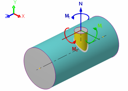 |
| Fig. 5.29. Local coordinate system for SIF calculation |
Table 5.5 shows the calculation of the stress intensification factors for local coordinate system of nozzle (fig. 5.29).
| Table 5.5. Stress intensification factors (SIF) | ||||||
| Description | Fatigue strength reduction factor | Stresses, MPa | Stress concentration/intensification factors | |||
| Max. | Nom. | |||||
| Kf | σMAX | σNOM | SCF | i (SIF) | ||
| From axial force N | ia | 1,3500 | 1050,2615 | 77,7000 | 14,5306 | 9,8082 |
| From inplane moment Mi | ii | 1,3500 | 276,9120 | 77,7000 | 3,8311 | 2,5860 |
| From outplane moment Mo | io | 1,3500 | 667,5290 | 77,7000 | 9,2354 | 6,2339 |
| From torsion moment Mt | it | 1,3500 | 252,0132 | 77,7000 | 3,4867 | 2,3535 |
| From design pressure p | ip | 1,3500 | 345,7572 | 77,7000 | 4,4499 | 3,0037 |
PASS/NOZZLE-FEM 3.5. Program Manual
Copyright © 2017-2026, PASS Team