

|
PASS/NOZZLE-FEM 3.5. Program Manual | |
Branch connection stiffness and flexibility is calculated for application point of forces (nozzle head) in each direction in local coordinates. As well as in global coordinates for nozzle head. At stiffness calculation of branch connection total allowances are not considered.
Total additions for wall thikness are not used for stitffness calculation procedure.
Nozzle stiffness is defined as ratio of applied force (moment) to corresponding displacement (degree of freedom):
| $$ K_i = \frac{F_i}{u_i} $$ | (5.15) |
where $F_i$ - unit force for i-th degree of freedom; $u_i$ - calculated value of i-th degree of freedom at the nozzle end.
If the stiffnesses is used together with the FE-beam model (for example, in PASS/START-PROF programm [30]), in which they model some equipment (for example, a non-standard tee in PASS/START-PROF [30]), then it is necessary to enable the option "Exclude the beam stiffness" (fig. 5.30).
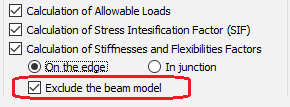 |
| Fig. 5.30. Including\excluding the beam stiffness |
With the beam stiffness exception, the program additionally determines the displacement at the nozzle branch end of beam model. In this case, calculated stiffnesses is determined by the relations:
| $$K_i = \frac{F_i}{u_i-u_{bi}}$$ | (5.16) |
where $u_{bi}$ - calculated value of i-th degree of freedom at nozzle end of beam model.
Note, the beam stiffness exception is not performed for model with bend (elbow).
The example of the stiffness calculation is given in the table 5.6.
| Table5.6. Stiffness at the nozzle end | ||||||
| Linear, kN/mm | Angular, kN·m/° | |||||
| KLx | KLy | KLz | KRx | KRy | KRz | |
| 59.1807 | 54.5664 | 67.9115 | 81.2115 | 761.1034 | 22.7687 | |
The flexibility values is defined as the inverse of the stiffness. Table 5.7 shows example of the flexibilities calculation.
| Table 5.7. Flexibility at the nozzle end | ||||||
| Linear, mm/kN | Angular, °/kN·m | |||||
| FLx | FLy | FLz | FRx | FRy | FRz | |
| 0.0169 | 0.0183 | 0.0147 | 0.0123 | 0.0013 | 0.0439 | |
Flexibility factors are computed for the runhead pipe, the bend (elbow) and also for the nozzle juncture and the elbow stanchion juncture when the option is included (fig. 5.30). They are used, as a rule, for transmission to other software that uses a beam-based calculation model. The flexibilities can to calculate by flexibility factors.
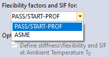 |
| Fig. 5.31. Setting formulas for calculating flexibility factors |
If ASME option (fig. 5.31) is selected then flexibility factors are calculated by the following formulas:
| $$\begin{array}{lll} k_{a} & = & \sqrt[3]{ \lambda_a \frac{3 E I_b}{D^3} }, \\ k_{i} & = & \lambda_i \frac{E I_b}{D}, \\ k_{o} & = & \lambda_o \frac{E I_b}{D}, \\ k_{t} & = & \lambda_t \frac{E I_b}{D}, \\ \end{array} $$ | (5.17) |
where $k_a$, $\lambda_a$ - the flexibility and flexibility factor from the axial force action on the nozzle; $k_i$, $\lambda_i$ - the flexibility and flexibility factor from the bending moment action inplane of device and nozzle; $k_o$, $\lambda_o$ - the flexibility and flexibility factor from the bending moment action outplane of device and nozzle; $k_t$, $\lambda_t$ - the flexibility and flexibility factor from the torsional moment action on the nozzle; $E$ - the elastic module; $I_b$ - the inertia moment of nozzle section; $D$ - the outside diameter for ASME VIII Div. 1, 2 [3] and the mean diameter for ASME B31J [5].
For other options, including the PASS/START-PROF program [30], the flexibility factors are defined as follows:
| $$ \begin{array}{lll} k_{a} & = & \lambda_a E A, \\ k_{i} & = & \lambda_i \frac{E I_b}{D_o}, \\ k_{o} & = & \lambda_o \frac{E I_b}{D_o}, \\ k_{t} & = & \lambda_t \frac{G I_p}{D_o}, \\ \end{array} $$ | (5.18) |
where $A$ - the area of nozzle section; $I_b$ - the inertia moment of nozzle section; $I_p$ - the polar inertia moment of nozzle section; $G$ - the shear modulus of nozzle material; $D_o$ - the nozzle outside diameter.
The flexibility factors for bend (elbow) is computed according to NB-3686.2 [2]:
| $$ \begin{array}{lll} k_{i} & = & \theta_i / \left(\frac{R}{E I_b}\int_0^\alpha{M(d\varphi)}\right), \\ k_{o} & = & \theta_o / \left(\frac{R}{E I_b}\int_0^\alpha{M(d\varphi)}\right), \\ k_{t} & = & \theta_t / \left(\frac{R}{G I_p}\int_0^\alpha{M(d\varphi)}\right). \\ \end{array} $$ | (5.19) |
where $\alpha$ - bend angle; $\theta_i$ - calculated rotation angle of the cross-section in the elbow plane; $\theta_o$ - calculated rotation angle of the cross-section out the elbow plane; $\theta_t$ - calculated rotation angle from torsional moment.
Table 5.8 shows the calculation of the flexibility factors.
| Table 5.8. Flexibility factors | ||
| Description | Values | |
| Axial from Fy | ka | 5.4614 |
| Inplane from Mx | ki | 4.0060 |
| Outplane from Mz | ko | 14.2885 |
| Torsion from My | kt | 0.3288 |
PASS/NOZZLE-FEM 3.5. Program Manual
Copyright © 2017-2026, PASS Team