

|
PASS/NOZZLE-FEM 3.5. Program Manual | |
The program PASS/NOZZLE-FEM provides two ways to set the calculated length of nozzle - "On the edge" and "In junction".
From version 2.16 each of these methods strictly corresponds to a specific calculation scheme. The flag choice affects all calculations categories: on strength, allowable loads, stiffness and stress intensification factors.
On the edge - a typical case when the nozzle and supply pipelines are connected by flange (fig. 5.24). In this case, the design scheme, including the supply pipelines, ends on a flange connection, and the design loads on the nozzle are obtained at this point.
The nozzle length $L_1$ is set by user and must not be less than the minimal length needed for create the correct finite element model:
| $$ L_1 \ge \max\left\{\Delta_n,r\right\} + \min\left\{s,s_1\right\},$$ | (5.10) |
where $\Delta_n$ is the weld size on the nozzle; $s_1$ is the nozzle thickness; $s$ is the thickness of the base element near the juncture.
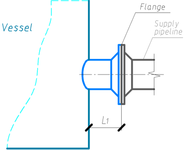 |
| Fig. 5.24. Design model "On the edge" |
In junction - a case when the supply pipeline ends at the place of junction into the shell (fig. 5.25). In this case, the design scheme, including the supply pipelines, usually ends on the outer surface of the shell, and the design loads on the nozzle are obtained at this point. The nominal nozzle length, starting with version 2.16, $L_1$ is defined from the condition of sufficient flexibility:
| $$ L_{min} = \min\left\{0.5d^{1.4}_{m}s^{-0.4}_1, d\right\},$$ | (5.11) |
where $d$ and $d_{m}$ are the inside and mean diameters of attached loaded nozzle (pipe) accordingly; $s_1$ is the nozzle thickness.
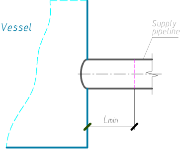 |
| Fig. 5.25. Design model "In junction" |
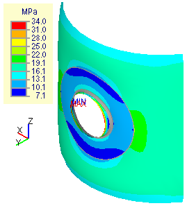
This length allows you to take into account the ovalization of the section in the area of the junction, which corresponds to the "flexible" connection of the pipeline with the shell [5]. In versions up to 2.16, in the choosing case “In junction”, the length was assumed to be as short as possible, which led to a more rigid instersection of the pipeline into the shell and incorrect stress defination of in junction area, since edge effects could have appeared from the place of application of the load on the nozzle (fig. 5.26).
 |
 |
 |
| a) | b) | c) |
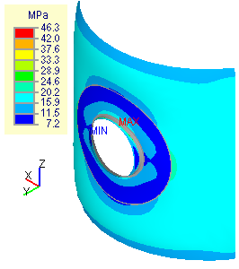
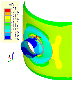
| Fig. 5.26. Total equivalent stresses on the outer surface: | ||
| a. $L_1=30mm$ - clearly visible edge loading effect; | ||
| b. $L_1=50mm$ - small nozzle length, falls into the region of the edge loading effect; | ||
| c. with the nozzle length, obtained by the formula (5.11). | ||
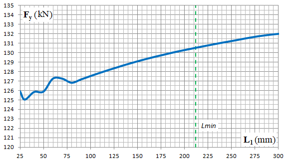
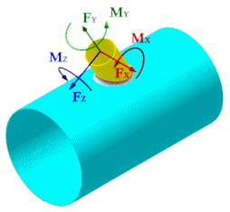
Fig. 5.27 shows a graph of changes in the allowable axial force $F_y$ depending on the nozzle length $L_1$, which shows that in the junction area at a distance of less than 100mm edge effects from the place of application of the load appear. The calculation results are presented for a tilted nozzle with an internal diameter of 203mm and a thickness of 6mm into shell with internal diameter 2000mm and thickness 12mm (fig. 5.27b).
 |
 |
| a) | b) |
| Fig. 5.27. Graph of changes in the allowable axial force $F_y$ depending on the nozzle length $L_1$ (a) for a tilted nozzle intersection in a cylindrical shell (b). | |
In the strength calculation, the loads, specified by the user in junction place, is automatically transformed to statically equivalent loads in the section with the length $L_1=L_{min}$ (fig. 5.28).
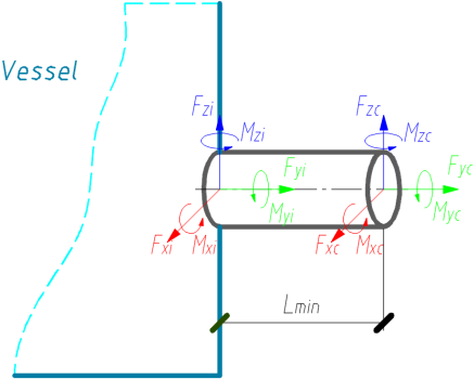 |
$$\begin{array}{l} F_{xc} = F_{xi} , \\ F_{yc} = F_{yi} , \\ F_{zc} = F_{zi} , \\ M_{xc} = M_{xi} - F_{zi}L_1 , \\ M_{yc} = M_{yi} , \\ M_{zc} = M_{zi} + F_{xi}L_1 . \end{array}$$ |
| Fig. 5.28. Loads recalculation on the nozzle in the design scheme "In junction". | |
PASS/NOZZLE-FEM 3.5. Program Manual
Copyright © 2017-2026, PASS Team