|
PASS/NOZZLE-FEM 3.6. Program Manual | |
The support leg model is specified by a trunnion type with a base element, by the dimensions and section parameters, by its placement way relative to the base element, etc.
The description of the base element is given in the section: Base element setting.
The program allows to insert a support legs on all types of base elements, except for vertical cylindrical vessels and bends.
Table 3.20 shows key features of the base element (shell).
| Table 3.20 | |||||||||||||||||||||||||
| Feature | Description | ||||||||||||||||||||||||
| Support local coordinate system (LCS), located on cylindrical or conical shells: |
X-axis is directed along the local (longitudinal) Z-axis of the base element. Y-axis is directed along the normal to the ZX-plane; it is calculated as $e_y = e_z \times e_x$. Z-axis is directed along the longitudinal support axis. The cross-section rotation angle $\omega_t$ allowes to rotate the local X and Y axes around the local Z-axis, 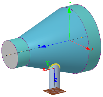 | ||||||||||||||||||||||||
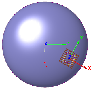
| Support local coordinate system (LCS), located on heads: |
X-axis is directed along a straight line in the head plane passing through the center of the head and the support end, that is from C-point to A-point (fig. 3.62). Y-axis is directed along the normal to the ZX-plane; it is calculated as $e_y = e_z \times e_x$. Z-axis is directed along the longitudinal support axis. If the support is central (offset is not set), then X-axis coincides with the local X-axis of the head. The cross-section rotation angle $\omega_t$ allowes to rotate the local X and Y axes around the local Z-axis, 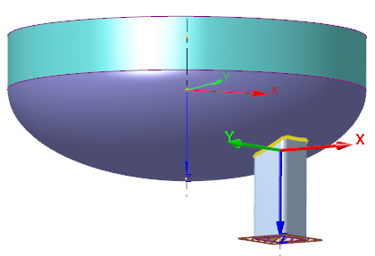
 | ||||||||||||||||||||||||
| Support local coordinate system (LCS), located on rectangular plate: |
It coincides with local CS of base element (plate). | ||||||||||||||||||||||||
| Placement in LCS of base element: | For cylindrical or conical shells, including tank and vertical vessel, the support placement can be specified by the following types:
For elbows (bends), the support placement can be specified by the same types as for the cylindrical shell.
For heads or rectangular plates, the placement of the support support can be specified by the following types:
| ||||||||||||||||||||||||
| Constraints (dof): | The support end is fixed in the stress analysis, and the ends of the base element are free. | ||||||||||||||||||||||||
| Support loads: | Thermal strains. More information in the section: Setting model loads. | ||||||||||||||||||||||||
| Shell loads: | Described in the section: Base element setting. | ||||||||||||||||||||||||
| Special calculations: | Allowable loads; Stiffness and flexibility factors; Stress intensification factors; Calculation as per WRC 537(107)/297 (only for circular and rectangular sections). | ||||||||||||||||||||||||
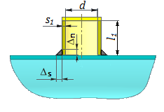
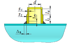
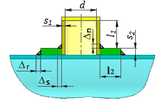
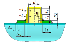
| Support junction types: |
The support design model corresponds to fig. 3.63.
| ||||||||||||||||||||||||

PASS/NOZZLE-FEM 3.6. Program Manual
Copyright © 2017-2026, PASS Team