

|
PASS/NOZZLE-FEM 3.5. Program Manual | |
After creating a new one, as well as opening an existing one of the file, the first panel is "Project properties", which contains the general project data (fig. 3.3).
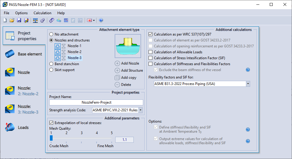 |
| Fig. 3.3. Panel for setting project common properties. |
The general data is:
The attachment type determines the kind of design scheme. For more information, see: Attachment setting.
Starting from version 3.5, the program allows to specify several attachments (nozzle and structure). Each such attachment must have a unique and non-empty name to uniquely identify it. These names are used in the user interface (attachment property sheet, defining loads), creating reports, etc. To specify multiple attachments, use the following control buttons:
| Button | Description |
| Add Nozzle | Allows to add a nozzle with unique default name. |
| Add Structure | Allows to add a structure attachment with unique name by default. |
| Add copy | Allows to copy the selected attachment (in the list of attachments) along with all its parameters and loads and with a new unique default name. |
| Delete | Allows to remove the selected attachment (in the list of attachments). |
 |
If it is blue, it indicates that this attachment is a nozzle. When pressed, it changes the type of attachment to a nozzle. |
 |
If it is blue, it indicates that this attachment is a structure. When pressed, it changes the type of attachment to a structure. |
The program provides a possibility of making calculations with use of one of five mesh levels. First level corresponds to the meshing with the least number of elements, which allows making calculations with minimum time and RAM con-sumption. Use of 5th mesh level allows making more precise calculation of deflected mode with maximum number of elements, but more time and RAM consump-tion. Allowable stress values depend on the mesh level. You may find more de-tailed information on interrelation between mesh quality and calculation results in "Calculation of deflected mode".
The user can set options for additional calculations:
| Options | Description |
| Define stiffness\flexibility and SIF at Ambient Temperature T0 |
The some codes require that flexibility analysis (stiffness\flexibility factors and SIF) is performed at ambient temperature (example, pp. 319.2.2(4), 319.4.4 ASME B31.3). This is because the calculation of fatigue strength is based on fatigue curves obtained by testing at ambient temperature of 21°C (70°C). |
| Output extreme values for calculation of allowable loads, stiffness\flexibility and SIF |
If the calculations of allowable loads, stiffness and SIF are carried out for different temperature groups, then this option forces to display their extreme values in the report. For example, for allowable loads and flexibility factors, the lowest values are displayed, and for stiffness and SIF, the maximum values are displayed. |
PASS/NOZZLE-FEM 3.5. Program Manual
Copyright © 2017-2026, PASS Team