Reservoir
To add
a new reservoir, click the button  of Components toolbar
and select the equipment type "Reservoir"
(or
use the corresponding item of "Insert
- Component - Equipment"
menu). Please note that
the new component is added to the project tree after the currently selected
element. Therefore, to add a new component after an existing one, select
it in the project tree or in the graphic window and add the new component.
If you need to add a new component to the beginning of a branch, select
the branch in the project tree and add the new component.
of Components toolbar
and select the equipment type "Reservoir"
(or
use the corresponding item of "Insert
- Component - Equipment"
menu). Please note that
the new component is added to the project tree after the currently selected
element. Therefore, to add a new component after an existing one, select
it in the project tree or in the graphic window and add the new component.
If you need to add a new component to the beginning of a branch, select
the branch in the project tree and add the new component.
The reservoir element is
used to model the hydrostatic head of the fluid contained in the reservoir
(or any other vessel/device) and to account for pressure losses at the
fluid abrupt acceleration/deceleration at entering the pipeline from reservoir
(or exiting from pipeline to reservoir). Reservoirs may
only be installed as the first or last element of the pipeline.
After adding a reservoir,
its characteristics will be displayed in the Object Properties Window:
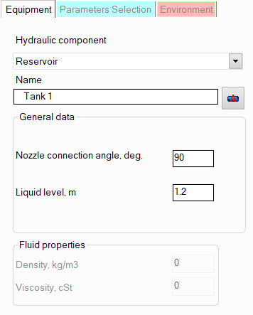
name -
by default, the name of any piping component coincides with its type,
but if necessary, the name can be changed in this field. When changing
the hydraulic component type (when selecting different types of equipment),
its name will also change, but only if it has not been previously
changed to another manually. Specify the name that you would like
to see for this element in reports with calculation results. To display
the name of a pipeline element on the diagram, click the corresponding
button to the right of its name;
nozzle
connection angle to the shell/bottom of the reservoir
- the default angle is 90° as
the most common case; if necessary, it can be replaced with another
one (depending on this angle, the hydraulic local resistance
of the nozzle edge may be slightly different);
liquid level -
the liquid level in a reservoir is the vertical distance between the
surface of the liquid in the reservoir and the center of the cross-section
of the nozzle to which the pipeline is connected. In the calculation,
the liquid level in the reservoir is considered constant, therefore,
to calculate systems with a variable liquid level in the tank, several
calculations can be performed sequentially, setting different values
of the liquid level.
Please note that the pressure at
the node with reservoir (which is usually a known value in hydraulic calculations)
should be specified equal the pressure "at the top" of the reservoir
(above the liquid level). If you specify the pressure at the inlet of
the flow into the pipeline as the pressure at the node, then you should
not enter the reservoir element in this case, since the liquid level is
already taken into account in the specified pressure value.
If it is necessary to model a "flow-through"
tank (or other similar apparatus),
then first of all it is necessary to understand whether a flow break occurs
in this equipment/tank:
if it occurs (i.e., the flow stream enters
the apparatus above the
liquid level in it), then the piping model in this place should
be "broken" - the points of flow entry into the equipment
and flow exit from it should be modeled as different pipeline
nodes (with different numbers), the same pressure values should
be specified for these nodes (equal to the pressure in the free
zone of the apparatus), the pipe
exit component should be added before the flow
entry node into the apparatus, and a reservoir with the corresponding
liquid level should be modeled right after the node of flow exit
from the apparatus into the pipeline;
if
there is no flow break in the apparatus (i.e., the flow enters
the apparatus below the
liquid level), then this apparatus should be modeled not as a
reservoir, but as a sequence of a pipe exit (simulating
the exit of the flow from the pipe into the apparatus), an elevation
change (simulating the "column
of liquid" between the center of the inlet and outlet pipes
of the apparatus) and a pipe entrance (simulating
the entry of the flow from the apparatus into the pipeline after
it).