Pipe entrance
To add
a pipe entrance, click the button  of Components toolbar
or use the corresponding item of "Insert
- Component" menu. Please note that the new component
is added to the project tree after the currently selected element. Therefore,
to add a new component after an existing one, select it in the project
tree or in the graphic window and add the new component. If you need to
add a new component to the beginning of a branch, select the branch in
the project tree and add the new component.
of Components toolbar
or use the corresponding item of "Insert
- Component" menu. Please note that the new component
is added to the project tree after the currently selected element. Therefore,
to add a new component after an existing one, select it in the project
tree or in the graphic window and add the new component. If you need to
add a new component to the beginning of a branch, select the branch in
the project tree and add the new component.
The pipe entrance component is used to model an abrupt acceleration of the flow when it enters from a region with an infinitely large cross-section (for example, from some equipment, reservoir or similar object of "large" dimensions compared to the pipe) into a region with a relatively small cross-section (into the pipe). In essence, it represents a limiting case of a sudden narrowing of the flow (when the narrowing occurs from an infinitely large value to a finitely small one).
After adding a pipe entrance, its characteristics will be displayed in the Object Properties Window:
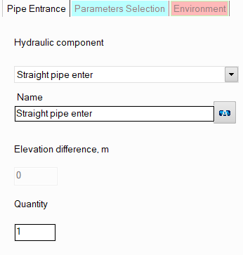
resistance type - here you need to specify the type of the pipe entrance - straight pipe enter or at 45° angle (the second is used in cases where the nozzle is not connected perpendicularly to the shell of the vessel/device, but, for example, at an angle to the bottom of the device). Depending on the angle of the inlet, its hydraulic resistance will be slightly different;
name - by default, the name of any piping component coincides with its type, but if necessary, the name can be changed in this field. When changing the hydraulic component type (when selecting different types of pipe entrances), its name will also change, but only if it has not been previously changed to another manually. Specify the name that you would like to see for this element in reports with calculation results. To display the name of a pipeline element on the diagram, click the corresponding button to the right of its name;
quantity - this parameter is usually not used for the pipe entrance. It is used for other piping components (for example, for valves or bends) when modeling several identical elements. In this case, you can enter the quantity of these elements in this field and the hydraulic resistance and heat losses of this element will be multiplied by the specified value. Since there are unlikely to be several pipe entrances in one pipeline branch, this option is of no practical interest for it.
Please note that from a hydraulic point of view, the entrance to the pipe is considered as a "point" (or "concentrated") resistance, having no length.