Reducer
To add
a new reducer, click the button  of Components toolbar
or use the corresponding item of "Insert
- Component" menu. Please note that the new component
is added to the project tree after the currently selected element. Therefore,
to add a new component after an existing one, select it in the project
tree or in the graphic window and add the new component. If you need to
add a new component to the beginning of a branch, select the branch in
the project tree and add the new component.
of Components toolbar
or use the corresponding item of "Insert
- Component" menu. Please note that the new component
is added to the project tree after the currently selected element. Therefore,
to add a new component after an existing one, select it in the project
tree or in the graphic window and add the new component. If you need to
add a new component to the beginning of a branch, select the branch in
the project tree and add the new component.
The reducer element is used to model
the hydraulic resistance caused by the flow contraction/expansion, as
well as friction losses and hydrostatic losses at the reducer if it is
smooth.
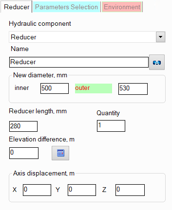
After adding a reducer, its characteristics
will be displayed in the Object Properties Window:
|
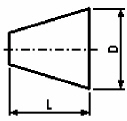
Reducer
(confuser or diffuser) |
For this type of reducer, it is necessary to
specify the value of the new internal and external diameter (after
the reducer) and its length. If the length is not specified, the
program assumes it to be equal to the length of the standard reducer
according to GOST 17378-2001 (version 2), OST 36-44-81
(molded reducers) or OST 36-22-77
depending on the diameters. |
|
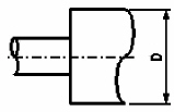
Sudden
contraction/expansion |
For
this type of reducer, it is necessary to specify the value of
the new internal and external diameter (after the reducer). |
The specified values
of the new inner and outer
diameters after the reducer are applied
to all components
of the branch after this component
until the end of the branch
or until the next component with
a diameter change (if there is one in this branch). Please note that when
adding and deleting reducers,
as well as when changing their new diameter value, the program will not
only automatically adjust the values of the diameters of all the following
components in this branch (up to the first element with a change in diameter
if any), but will also change the values of the radii of the bends
and elbows in this branch if they are equal to the standard value of 1.5*DN (for
pipes with DN < 500mm) or 1*DN (for pipes with DN >=
500mm).
name -
by default, the name of any piping component coincides with its type,
but if necessary, the name can be changed in this field. When changing
the hydraulic component type (when selecting different types of reducers),
its name will also change, but only if it has not been previously
changed to another manually. Specify the name that you would like
to see for this element in reports with calculation results. To display
the name of a pipeline element on the diagram, click the corresponding
button to the right of its name;
quantity -
this parameter is usually not used for reducers. It is used for other
piping components (for example, for fittings) when modeling several
identical elements. In this case, you can enter the quantity of these
elements in this field and the hydraulic resistance and heat losses
of this element will be multiplied by the specified value. Since there
are unlikely to be several identical reducers in one pipeline branch,
this option is of no practical interest for it;
elevation difference -
the elevation difference of a reducer is the vertical distance between
the center of its outlet and inlet cross-sections (a positive difference
means that the component's exit point is located higher than the entry
point, a negative difference means the opposite). Please note that
it is not necessary to set the elevation difference for reducer manually
- this parameters can be automatically calculated based on the specified
directions of the pipes before and after the reducer and the reducer
length by clicking the "Recalc by graphics" button (in the
form of a blue "calculator") for this reducer in the Object
Properties Window or by enabling the "Recalculate elevations
and angles on graphic before every analysis" option in the
program settings (in
the second case, before each calculation, the program will automatically
recalculate the elevation differences on all pipeline elements, bend
angles, etc. and store/correct them in the input data). To display
the "Recalc by graphics" button, do not forget to enable
the "Scaled graphic view" and "Show all components"
options in the pipeline graphic view options (on the View
Options toolbar); in addition, the "Precise graphic representation
of scaled view" option must be enabled in the
program settings;
axis offset -
for eccentric reducers, you can enter the axis offset value along
each of the coordinate axes for a more accurate display of the reducer
on the diagram and to take into account the difference in height on
it (if the offset occurs in the vertical plane).
A
sudden contraction/expansion is considered from a hydraulic point of view
as a "point" (or "concentrated") resistance, which
has no length, while a smooth reducer is considered as a "dimensional",
that is, having length, resistance.