
Learn about START-PROF pipe stress analysis software
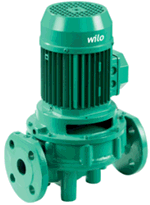
Model in-line pumps as rigid elements similar to valves.
The software performs allowable load checks per selected industry standards.
Review results in the Loads on Nozzles and Equipment Table.
See also: Nozzle Load Reduction Techniques in START-PROF
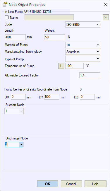
Property |
Description |
Code |
Supported design codes:
|
Name |
Element identifier. Enable to display in 3D view. |
Length |
Overall length including adjoining flanges (face-to-face dimension) |
Weight |
Pump weight including flanges. Excludes insulation and fluid content. Standard weight without overload factors. Fluid and insulation weights apply overload factors from connected pipes. |
Material |
Material selection from materials database |
Manufacturing Technology |
Seamless pipe uses Wl=1.0 for ASME B31.1, B31.3, DL/T 5366-2014. Electric-welded pipe Wl values from database. Details... GOST 32388-2013 uses different material databases for seamless/welded pipe types. |
Temperature |
Pump operating temperature. Adjust per operation mode.
View all mode values using |
Allowable Exceed Factor |
API 610 default: 2.0
Other codes default: 1.4. Adjust per manufacturer specifications.
|
Vertical in-line pumps with unanchored supports may use twice the Table 5 allowable values for side nozzles.

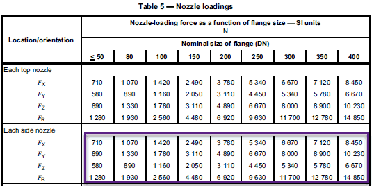
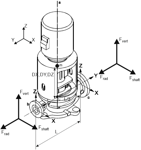
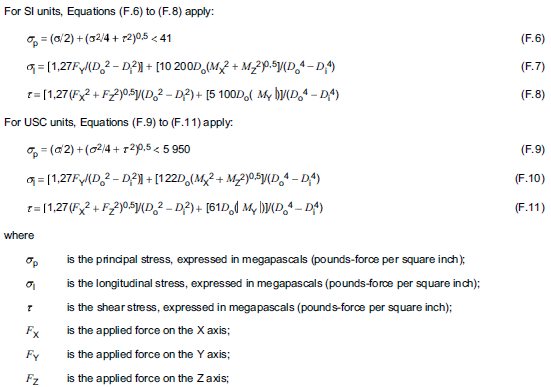
For exceeded nozzle loads, apply API 610 Annex F evaluation methods.
Insert in-line pump at selected node: Insert > Equipment > In-line Pump