

|
PASS/NOZZLE-FEM 3.5. Program Manual | |
Stiffness and flexibility calculation of junction between nozzle and vessel is made in three directions:
| - | linear stiffness along the nozzle axis (axial), $K_R$; |
| - | angular stiffness in transverse plane of the shell, $K_{\theta}$; |
| - | angular stiffness in longitudinal plane of the shell, $K_L$. |
Flexibilities corresponding to the above stiffnesses, represent themselves reciprocal variables $\displaystyle\frac{1}{K_R}$, $\displaystyle\frac{1}{K_{\theta}}$ and $\displaystyle\frac{1}{K_L}$.
Connections between nozzle and shell in other three directions are taken as absolutely stiff ones. It that case flexibilities are set equal to zero.
If the type of branch connection do not meet application conditions (for instance, tilted nozzle), then use of finite element method will be worthwhile.
Calculation of axial stiffness of nozzle junction into the cylindrical shell is made by means of nondimensional parameter relations $\displaystyle\delta\frac{ER_m}{F_R}$ of branch connection geometrical characteristics $\displaystyle\left(\frac{R_m}{s}\right)$, $\displaystyle\left(\frac{C}{R_m}\right)$ and $\displaystyle\left(\frac{L_e}{R_m}\right)$ in according to [18] (fig. 5.37).
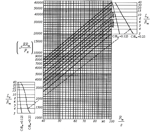 |
| Fig. 5.37. Relative radial displacement of shell in the junction |
In the course of parameter calculations the following notations are used:
| $\delta$ | - | nozzle axial displacement; | $R_m = 0.5(D+s)$ | - | mean radius of cylindrical shell, without regard to corrosion; | $L_e$ | - | reduced radius of nozzle. |
In case of nozzle-axis offset by $l$ relative to the shell centre:
| $$ L_e = L - 4\frac{l^2}{L}, $$ | (5.107) |
where $l = |0.5L-L_n|$ (fig. 5.38).
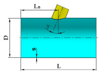 |
| Fig. 5.38. Nozzle placement |
Nozzle axial stiffness (radial stiffness of the shell) in junction zone shall be calculated as:
| $$ K_R = \frac{F_R}{\delta} = \frac{ER_m}{\displaystyle\delta\frac{ER_m}{F_R}}. $$ | (5.108) |
Calculation of bending stiffness of branch connection in the transverse plane $K_{\theta}$ and longitudinal plane $K_L$ of the shell is made by means of nondimensional parameter relations $\displaystyle\frac{M_{\theta(L)}}{Es^3\varphi_{\theta(L)}}$ of branch connection geometrical characteristics $\displaystyle\lambda=\frac{d+2s_1}{2R_m}\sqrt{\frac{2R_m}{s}}$, $\displaystyle\Lambda=\frac{L_{eb}}{\sqrt{2R_ms}}$ and $\displaystyle\left(\frac{s}{s_1}\right)$, illustrated in fig. 5.39 and 5.40.
| Here | $\displaystyle M_{\theta(L)}$ | - | bending moment in transverse direction ($\theta$) and longitudinal direction ($L$) of the shell correspondingly; |
| $\displaystyle\varphi_{\theta(L)}$ | - | nozzle rotation angle from bending moment in transverse direction ($\theta$) and longitudinal direction ($L$) correspondingly; | |
| $\displaystyle L_{eb} = \frac{2L^2-8L^2_e}{L+2\sqrt(0.25L^2-L^2_{\phi})}$ | - | effective length of shell for calculation of bending stiffness. |
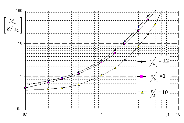 |
| Fig. 5.39. Relative angular displacement in longitudinal plane at $\Lambda \ge 10$ |
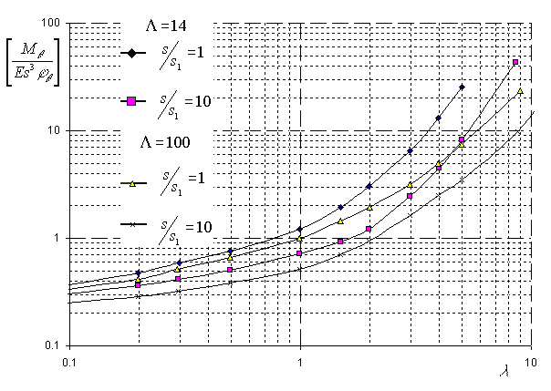 |
| Fig. 5.40. Relative angular displacement in transverse plane of the shell |
Bending stiffness in circumferential and longitudinal directions:
| $$ K_{\theta(L)} = \frac{M_{\theta(L)}}{\varphi_{\theta(L)}} = Es^3\left(\frac{M_{\theta(L)}}{Es^3\varphi_{\theta(L)}}\right). $$ | (5.109) |
The presence of a pad stiffness of nozzle's junction depends on its width $l_2$ and thickness $s_2$. In the course of stiffness calculation it is supposed that nozzle displacements under the influence of force factors are to be calculated as a sum of nozzle displacements with diameter $d+2s_1$ incut into the shell with thickness $s+s_2$ and nozzle displacements with nominal diameter $d+2(s_1+l_2)$ and shell with thickness $s$ [9].
Stiffness (flexibility) of nozzle reinforced by beading is calculated the same way as for nonreinforced nozzle. At the same time a nozzle reinforced by weld-in torus insertion or weld-in ring is calculated as a nozzle reinforced by pad. As a width of doubling plate a width of torus insertion is taken. Instead of calculation thickness $s_p = (s+s_2)$ a width of torus insertion (weld-in ring) $s^*$ is taken.
If passing nozzles are used, internal parts are ignored in the course of stiffness calculation.
Calculation of stiffness in the nozzle junction zone into the spherical shell along the nozzle axis is made by means of nondimensional parameter relations $\displaystyle\left[\delta\frac{Es^2}{F_R R_m}\right]$ of geometrical adjective of branch connection parts $\displaystyle\left[u = 0.91\frac{d+s_1}{\sqrt{R_m s}}\right]$, illustrated in fig. 5.41.
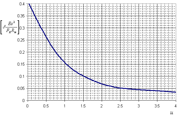 |
| Fig. 5.41. Relative radial movement of nozzle |
Design model of nozzle junction into the spherical shell, as with strength calculations, can also be used for stiffness calculation of the nozzle junction into the elliptic head.
Shell radial stiffness in junction zone of the nozzle shall be calculated as follows:
| $$ K_R = \frac{Es^2}{\displaystyle R_m\left[\delta\frac{Es^2}{F_R R_m}\right]}. $$ | (5.110) |
For calculation of bending stiffness of the nozzle junction in the plane of moment $M$ action, nondimensional parameter relation $\displaystyle\left[\frac{\delta}{M}\frac{Es^2}{\displaystyle\sqrt{\frac{R_m}{s}}}\right]$ of geometrical adjective of connection parts $\displaystyle\left[u = 0.91\frac{d+s_1}{\sqrt{R_m s}}\right]$, illustrated in fig. 5.42.
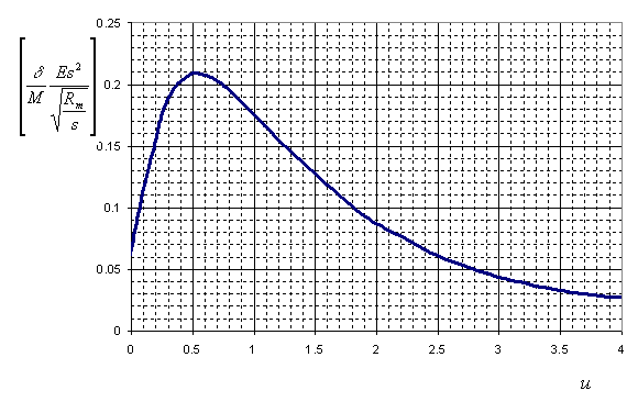 |
| Fig. 5.42. Relative radial movement of nozzle edge |
As per the movements obtained the angular movements of nozzle axis are calculated:
| $$ \varphi = \frac{2\delta}{d+s_1}. $$ | (5.111) |
So, bending stiffness of branch connection:
| $$ K_b = \frac{M}{\varphi} = \frac{d+s_1}{2}\frac{Es^2}{\displaystyle\sqrt{\frac{R_m}{s}}\left[\frac{\delta}{M}\frac{Es^2}{\displaystyle\sqrt{\frac{R_m}{s}}}\right]}. $$ | (5.112) |
For stiffness calculation of branch connection, in the presence of pad, beading, weld-in torus insertion or weld-in ring, one shall use the assumptions taken for cylindrical shell.
PASS/NOZZLE-FEM 3.5. Program Manual
Copyright © 2017-2026, PASS Team