

|
PASS/NOZZLE-FEM 3.5. Program Manual | |
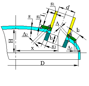
Design model of junction between nozzle and vessel wall is shown at fig. 5.36.
 |
 |
| Fig. 5.36. Design model of junction between nozzle and vessel wall | |
Design model of nozzle junction into the spherical shell can also be used for strength and stiffness calculation of the nozzle junction into the elliptic head.
At that to determine $R_m$ value, the elliptic head design diameter is used instead diameter $D$ (fig. 5.36):
| $$ D_{p} = \frac{D^2}{2H}\sqrt{1-4\frac{D^2-4H^2}{D^4}x^2}. $$ | (5.60) |
In the stress calculations in spherical shell the relative nondimensional forces and moments are used, which depend on geometric parameters of the shell and nozzle $U$, $\gamma$ and $\rho$.
Nondimensional geometrics:
| $$ U = \frac{r_0}{\sqrt{R_m(s-c)}}, $$ | (5.61) |
| $$ \gamma = \frac{r_m}{\sqrt{R_m(s_1-c_s)}}, $$ | (5.62) |
| $$ \rho = \frac{s-c}{s_1-c_s}, $$ | (5.63) |
where $r_m = 0.5(d+s_1+c_s)$ - branch pipe mean radius.
Relative nondimensional forces and moments in tangential ($\theta$) direction:
| $n_{\theta F}$ | - | membrane force due to $F_R$ |
| $m_{\theta F}$ | - | bending moment due to $F_R$ |
| $n_{\theta M}$ | - | membrane force due to $M_{1(2)}$; |
| $m_{\theta M}$ | - | bending moment due to $M_{1(2)}$. |
Relative nondimensional forces and moments in radial ($X$) direction:
| $n_{RF}$ | - | membrane force due to $F_R$ |
| $m_{RF}$ | - | bending moment due to $F_R$ |
| $n_{RM}$ | - | membrane force due to $M_{1(2)}$; |
| $m_{RM}$ | - | bending moment due to $M_{1(2)}$. |
Tangential membrane stresses of $F_R$ force:
| $$ \sigma_{m\theta}(F_R) = n_{\theta F} \frac{F_R}{R_m(s-c)}, $$ | (5.64) |
where $n_{\theta F}$ is assigned as per [8].
Tangential bending stresses from $F_R$ force:
| $$ \sigma_{b\theta}(F_R) = m_{\theta F} \frac{6F_R}{(s-c)^2}, $$ | (5.65) |
where $m_{\theta F}$ is assigned as per [8].
Radial membrane stresses of $F_R$ force:
| $$ \sigma_{mx}(F_R) = n_{RF} \frac{F_R}{(s-c)^2}, $$ | (5.66) |
where $n_{RF}$ is assigned as per [8].
Radial bending stresses from $F_R$ force:
| $$ \sigma_{bR}(F_R) = m_{RF} \frac{6F_R}{(s-c)^2}, $$ | (5.67) |
where $m_{RF}$ is assigned as per [8].
Tangential membrane stresses in design points 5-8 from the moment $M_1$ and points 1-4 from the moment $M_2$:
| $$ \sigma_{m\theta}(M) = n_{\theta M} \frac{M}{(s-c)^2\sqrt{R_m(s-c)}}, $$ | (5.68) |
where $n_{\theta M}$ is assigned as per [8].
Tangential bending stresses in design points 5-8 from the moment $M_1$ and points 1-4 from the moment $M_2$:
| $$ \sigma_{b\theta}(M) = m_{\theta M} \frac{6M}{(s-c)^2\sqrt{R_m(s-c)}}, $$ | (5.69) |
where $m_{\theta M}$ is assigned as per [8].
Radial membrane stresses in design points 5-8 from the moment $M_1$ and points 1-4 from the moment $M_2$:
| $$ \sigma_{mR}(M) = n_{RM} \frac{M}{(s-c)^2\sqrt{R_m s}}, $$ | (5.70) |
where $n_{RM}$ is assigned as per [8].
Radial bending stresses in design points 5-8 from the moment $M_1$ and points 1-4 from the moment $M_2$:
| $$ \sigma_{bR}(M) = m_{RM} \frac{6M}{(s-c)^2\sqrt{R_m s}}, $$ | (5.71) |
where $m_{RM}$ is assigned as per [8].
Due to the torsional moment shearing stresses arises in the junction between nozzle and shell:
| $$ \tau_{\theta x} = \frac{M_T}{2\pi r^2_0 (s-c)}. $$ | (5.72) |
Forces $F_1$ in points 5-8 and $F_2$ in points 1-4 cause shear membrane stresses:
| $$ \tau_{x \theta} = \frac{F_{1(2)}}{\pi r_0 (s-c)}. $$ | (5.73) |
Local membrane stresses from internal pressure are calculated depending on stress intensification factor, obtained for cross section of the shell $I_{\theta p} = I_{xp}$ (fig. 5.36).
Circumferential stress from internal pressure in all design points:
| $$ \sigma_{\theta p} = p I_{\theta p} \frac{D+(s+s_2-c)}{2(s+s_2-c)}, $$ | (5.74) |
Longitudinal (radial) stress from internal pressure in all design points is calculated by equation (5.74) at $I_{\theta p} = 1$.
If a calculation ratio is $I_{\theta p} < 1$, then a stress intensification factor $0.5(1+I_{\theta p})$ is uses for calculation of circumferential and axial stresses in all design points of branch connection.
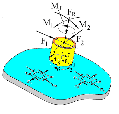
In general, all the external loads applied to the nozzle can be distributed by three directions, i.e. can be shown as simultaneously acting forces $F_R$, $F_1$, $F_2$ and moments $M_1$, $M_2$, $M_t$. After calculation of stresses from effective forces and pressure, total stresses in design points (1-8) are calculated with taking into consideration of signs (table 5.16).
In the presence of corrosive hydrogen sulphide environment, a supplementary calculation of tensile stresses on the inside surfaces of the shell is made (2, 4, 6, 8 points):
| $$ \sigma_{in} = \max{\left\{ \frac{1}{2} \left( \sigma_{\theta}+\sigma_x+\sqrt{(\sigma_{\theta}-\sigma_x)^2+4\tau^2_{\theta x}} \right); 0 \right\}}. $$ | (5.75) |
| Table 5.16. Local stresses in spherical shell in the nozzle junction zone operating under influence of internal pressure and external loads, as per WRC 107 | ||||||||
| Circumferential stresses (relative to branch pipe), $\sigma_{\theta}$ | 1 | 2 | 3 | 4 | 5 | 6 | 7 | 8 |
| Membrane from $F_R$ | - | - | - | - | - | - | - | - |
| Bending from $F_R$ | - | + | - | + | - | + | - | + |
| Membrane from $M_1$ | - | - | + | + | ||||
| Bending from $M_1$ | - | + | + | - | ||||
| Membrane from $M_2$ | - | - | + | + | ||||
| Bending from $M_2$ | - | + | + | - | ||||
| Circumferential stresses from pressure $\sigma_{\theta p}$ | + | + | + | + | + | + | + | + |
| Total circumferential membrane stresses $\sigma_{m\theta}$ | ||||||||
| Total circumferential stresses $\sigma_{\theta}$ (eq. 5.3.1) | ||||||||
| Radial stresses (relative to branch pipe), $\sigma_x$ | 1 | 2 | 3 | 4 | 5 | 6 | 7 | 8 |
| Membrane from $F_R$ | - | - | - | - | - | - | - | - |
| Bending from $F_R$ | - | + | - | + | - | + | - | + |
| Membrane from $M_1$ | - | - | + | + | ||||
| Bending from $M_1$ | - | + | + | - | ||||
| Membrane from $M_2$ | - | - | + | + | ||||
| Bending from $M_2$ | - | + | + | - | ||||
| Radial stresses from pressure $\sigma_{xp}$ | + | + | + | + | + | + | + | + |
| Total longitudinal membrane stresses $\sigma_{mx}$ | ||||||||
| Total longitudinal stresses $\sigma_{x}$ (eq. 5.3.1) | ||||||||
| Shearing stresses from $M_t$ | + | + | + | + | + | + | + | + |
| Shearing stresses from $F_1$ | - | - | + | + | ||||
| Shearing stresses from $F_2$ | + | + | - | - | ||||
| Total shearing stresses $\tau_{\theta x}$ | ||||||||
| Reduced total stresses $\sigma_{eqv}$ | ||||||||
| Tensile stresses on the shell inside surface $\sigma_{in}$ | ||||||||
PASS/NOZZLE-FEM 3.5. Program Manual
Copyright © 2017-2026, PASS Team