

|
PASS/NOZZLE-FEM 3.5. Program Manual | |
In the stress calculations in cylindrical shell the relative nondimensional forces and moments are used, which depend on geometric parameters of the shell $\gamma = \displaystyle\frac{R_m}{(s-c)}$ and nozzle $\beta = \displaystyle\frac{0.875 r_0}{R_m}$ [8], where $R_m = \displaystyle\frac{(D+s+c)}{2}$ - mean radius of the shell; $r_0 = \displaystyle\frac{d+2s_1}{2}$ - nozzle outer radius.
Relative nondimensional forces and moments in circumferential direction:
| $n_{\theta F}$ | - | membrane force due to $F_R$ |
| $m_{\theta F}$ | - | bending moment due to $F_R$ |
| $n_{\theta MC}$ | - | membrane force due to $M_C$; |
| $m_{\theta MC}$ | - | bending moment due to $M_C$ |
| $n_{\theta ML}$ | - | membrane force due to $M_L$; |
| $m_{\theta ML}$ | - | bending moment due to $M_L$. |
Relative nondimensional forces and moments in longitudinal direction:
| $n_{\theta XF}$ | - | membrane force due to $F_R$ |
| $m_{\theta XF}$ | - | bending moment due to $F_R$ |
| $n_{\theta XMC}$ | - | membrane force due to $M_C$; |
| $m_{\theta XMC}$ | - | bending moment due to $M_C$ |
| $n_{\theta XML}$ | - | membrane force due to $M_L$; |
| $m_{\theta XML}$ | - | bending moment due to $M_L$. |
Circumferential membrane stresses of $F_R$ force:
| $$ \sigma_{m\theta}(F_R) = n_{\theta F} \frac{F_R}{R_m(s-c)}, $$ | (5.33) |
where $n_{\theta F}$ is assigned as per [8].
Circumferential bending stresses of $F_R$ force:
| $$ \sigma_{b\theta}(F_R) = m_{\theta F} \frac{6F_R}{(s-c)^2}, $$ | (5.34) |
where $m_{\theta F}$ is assigned as per [8].
Longitudinal membrane stresses of $F_R$ force:
| $$ \sigma_{mx}(F_R) = n_{XF} \frac{F_R}{R_m(s-c)}, $$ | (5.35) |
where $n_{XF}$ is assigned as per [8].
Longitudinal bending stresses of $F_R$ force:
| $$ \sigma_{bx}(F_R) = m_{XF} \frac{6F_R}{(s-c)^2}, $$ | (5.36) |
where $m_{XF}$ is assigned as per [8].
Circumferential membrane stresses from $M_C$ moment:
| $$ \sigma_{m\theta}(M_C) = n_{\theta MC} \frac{M_C}{R^2_m\beta(s-c)}, $$ | (5.37) |
where $n_{\theta MC}$ is assigned as per [8].
Circumferential bending stresses of $M_C$:
| $$ \sigma_{b\theta}(M_C) = m_{\theta MC} \frac{6M_C}{R_m\beta(s-c)^2}, $$ | (5.38) |
where $m_{\theta MC}$ is assigned as per [8].
Longitudinal membrane stresses of $M_C$:
| $$ \sigma_{mx}(M_C) = n_{XMC} \frac{M_C}{R^2_m\beta(s-c)}, $$ | (5.39) |
where $n_{XMC}$ is assigned as per [8].
Longitudinal bending stresses of $M_C$:
| $$ \sigma_{bx}(M_C) = m_{XMC} \frac{6M_C}{R_m\beta(s-c)^2}, $$ | (5.40) |
where $m_{XMC}$ is assigned as per [8].
Circumferential membrane stresses of $M_L$:
| $$ \sigma_{m\theta}(M_L) = n_{\theta ML} \frac{M_L}{R^2_m\beta(s-c)}, $$ | (5.41) |
where $n_{\theta ML}$ is assigned as per [8].
Circumferential bending stresses of $M_L$:
| $$ \sigma_{b\theta}(M_L) = m_{\theta ML} \frac{6M_L}{R_m\beta(s-c)^2}, $$ | (5.42) |
where $m_{\theta ML}$ is assigned as per [8].
Longitudinal membrane stresses of $M_L$:
| $$ \sigma_{mx}(M_L) = n_{XML} \frac{M_L}{R^2_m\beta(s-c)}, $$ | (5.43) |
where $n_{XML}$ is assigned as per [8].
Longitudinal bending stresses of $M_L$:
| $$ \sigma_{bx}(M_L) = m_{XML} \frac{6M_L}{R_m\beta(s-c)^2}, $$ | (5.44) |
where $m_{XML}$ is assigned as per [8].
Due to the torsional moment shearing stresses are created in the junction between nozzle and shell:
| $$ \tau_{\theta x} = \frac{M_T}{2 \pi r^2_0 (s-c)}. $$ | (5.45) |
Forces $F_C$ and $F_L$ causes shear stresses in longitudinal (1-4) and circumferential (5-8) section correspondingly:
| $$ \tau_{x\theta} = \frac{F_C}{\pi r_0 (s-c)}, $$ | (5.46) |
| $$ \tau_{\theta x} = \frac{F_L}{\pi r_0 (s-c)}. $$ | (5.47) |
The method offered is based on two allowances [19]:
| 1. | Average stresses in design zone of hole reinforcement $\sigma_{\theta(x)cp}$ are calculated on the basis of ratio of the pressure force towards cross section area within the design zone. |
| 2) | Membrane stresses have a linear distribution along the zone of hole reinforcement (fig. 5.33), where |
| $\sigma_{\theta(x)0}$ | - | stresses in the shell beyond the design zone; |
| $\sigma_{\theta(x)ср}$ | - | mean stresses in the middle of the design zone of hole reinforcement; |
| $\sigma_{\theta(x)р}$ | - | local membrane stresses in design points of junction between nozzle and shell. |
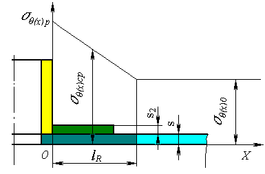 |
| Fig. 5.33. Stress distribution in the nozzle design zone |
Membrane stresses in design points:
| $$ \sigma_{\theta(x)p} = 2\sigma_{\theta(x)cp} - \sigma_{\theta(x)0}. $$ | (5.48) |
Local circumferential membrane stress from internal pressure in the nozzle junction can be shown as follows:
| $$ \sigma_{\theta p} = p I_{\theta p} \frac{D+(s+s_2-c)}{2(s+s_2-c)}, $$ | (5.49) |
where $I_{\theta p}$ - stress intensification factor from pressure in longitudinal section of shell (points 1-4, fig. 5.32). For cross section (points 5-8, fig. 5.32) $I_{\theta p} = 1$.
Design model for definition of intensification factor in longitudinal section is shown in fig. 5.34:
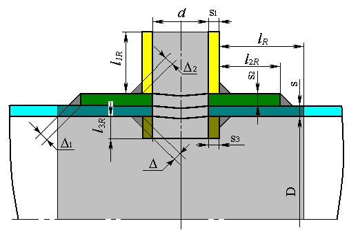 |
| Fig. 5.34. Design model of the nozzle in the shell longitudinal section |
Stress intensification factor against internal pressure in longitudinal section:
| $$ I_{\theta p} = \frac{2 (s+s_2-c)\left[ (d+2c_s)(l_{1R}-c) + (D+2c)(l_{R}+s_1+0.5d) \right]} {\left( D+(s+s_2-c) \right) \left[ l_R(s-c)+l_{1R}(s_1-c_s)+l_{2R}s_2+l_{3R}(s_3-2c_s)+(\Delta^2+\Delta^2_1+\Delta^2_2) \right]} - 1, $$ | (5.50) |
where design length of shell:
| $$ l_{R} = \left\{ \begin{array}{lll} \min{\left\{ 8(s-c); \sqrt{2D(s-c)} \right\}}, & s_2 < 0.5(s-c), & \\ \min{\left\{ 10(s-c); \sqrt{2D(s-c)} \right\}}, & s_2 > 0.5(s-c), & l_2 \ge 2(s-c), \\ \min{\left\{ 8(s+s_2-c); \sqrt{2D(s-c)} \right\}}, & s_2 > 0.5(s-c), & l_2 \ge 2(s+s_2-c); \\ \end{array} \right. $$ | (5.51) |
design length of nozzle outer part:
| $$ l_{1R} = \min{\left\{ 8(s-c); s+s_2-c+0.55\sqrt{d(s_1-c_s)}+0.5\Delta_2 \right\}}; $$ | (5.52) |
design length of pad:
| $$ l_{2R} = \min{\left\{ l_2; l_R \right\}}; $$ | (5.53) |
design length of nozzle internal part:
| $$ l_{3R} = \min{\left\{ l_3; 8(s+s_2-c); 0.55\sqrt{d(s_3-c_s)}+0.5\Delta \right\}}. $$ | (5.54) |
Local longitudinal membrane stress from internal pressure:
| $$ \sigma_{xp} = p I_{xp} \frac{D+(s+s_2-c)}{4(s+s_2-c)}. $$ | (5.55) |
Design model for definition of intensification factor in cross section is shown in fig. 5.35:
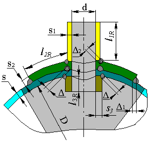 |
| Fig. 5.35. Design model of the nozzle in the shell cross section |
Stress intensification factor from internal pressure in cross-section is:
| $$ I_{xp} = \frac{2 (s+s_2-c)\left[ 2(d+2c_s)(l_{1R}-c) + (D+2c)(l_{R}+s_1+0.5d) \right]} {\left( D+(s+s_2-c) \right) \left[ l_R(s-c)+l_{1R}(s_1-c_s)+l_{2R}s_2+l_{3R}(s_3-2c_s)+(\Delta^2+\Delta^2_1+\Delta^2_2) \right]} - 1, $$ | (5.56) |
For longitudinal section (points 1-4) $I_{xp} = 1$.
As the design coefficients $I_{\theta(x)p} < 1$, then the following equations are used for calculation of circumferential and longitudinal stresses in all design points of branch connection:
| $$ \sigma_{\theta p} = p \frac{1+I_{\theta p}}{2} \frac{D+(s+s_2-c)}{2(s+s_2-c)}, $$ | (5.57) |
| $$ \sigma_{xp} = p \frac{1+I_{xp}}{2} \frac{D+(s+s_2-c)}{4(s+s_2-c)}. $$ | (5.58) |
When $l_2 < 8(s+s_2-c)$ at calculation of stresses and stress intensification factor it is necessary to substitute $s$ for $s+s_2$ (pad thickness is neglected).
Stresses on the pad edge are calculate as per (5.49), (5.55) under the assumption $I_p = 1$, $s_2 = 0$.
In general, all the external loads applied to the nozzle can be distributed by three directions, i.e. can be shown as simultaneously acting forces $F_R$, $F_C$, $F_L$ and moments $M_C$, $M_L$, $M_t$. After calculation of stresses from effective forces and pressure, total stresses in design points (1-8) are calculated with taking into consideration of signs (table 5.15.
In the presence of corrosive hydrogen sulphide environment, a supplementary calculation of tensile stresses on the shell inside surfaces of the nozzle is made (2, 4, 6, 8 points):
| $$ \sigma_{in} = \max{\left\{ \frac{1}{2} \left( \sigma_{\theta}+\sigma_x+\sqrt{(\sigma_{\theta}-\sigma_x)^2+4\tau^2_{\theta x}} \right); 0 \right\}}. $$ | (5.59) |
| Table 5.15. Local stresses (taking into account the signs) of the nozzle in branch connection design points loaded by the internal pressure and external loads as per WRC 107 | ||||||||
| Circumferential stresses, $\sigma_{\theta}$ | 1 | 2 | 3 | 4 | 5 | 6 | 7 | 8 |
| Membrane from $F_R$ | - | - | - | - | ||||
| Membrane from $F_R$ | - | - | - | - | ||||
| Bending from $F_R$ | - | + | - | + | ||||
| Bending from $F_R$ | - | + | - | + | ||||
| Membrane from $M_C$ | - | - | + | + | ||||
| Bending from $M_C$ | - | + | + | - | ||||
| Membrane from $M_L$ | - | - | + | + | ||||
| Bending from $M_L$ | - | + | + | - | ||||
| Circumferential stresses from pressure $\sigma_{\theta p}$ | + | + | + | + | + | + | + | + |
| Total circumferential membrane stresses $\sigma_{m\theta}$ | ||||||||
| Total circumferential stresses $\sigma_{\theta}$ | ||||||||
| Longitudinal stresses, $\sigma_x$ | 1 | 2 | 3 | 4 | 5 | 6 | 7 | 8 |
| Membrane from $F_R$ | - | - | - | - | ||||
| Membrane from $F_R$ | - | - | - | - | ||||
| Bending from $F_R$ | - | + | - | + | ||||
| Bending from $F_R$ | - | + | - | + | ||||
| Membrane from $M_C$ | - | - | + | + | ||||
| Bending from $M_C$ | - | + | + | - | ||||
| Membrane from $M_L$ | - | - | + | + | ||||
| Bending from $M_L$ | - | + | + | - | ||||
| Longitudinal stresses from pressure $\sigma_{xp}$ | + | + | + | + | + | + | + | + |
| Total longitudinal membrane stresses $\sigma_{mx}$ | ||||||||
| Total longitudinal stresses $\sigma_{x}$ | ||||||||
| Shearing stresses from $M_t$ | + | + | + | + | + | + | + | + |
| Shearing stresses from $F_C$ | + | + | - | - | ||||
| Shearing stresses from $F_L$ | - | - | + | + | ||||
| Total shearing stresses $\tau_{\theta x}$ | ||||||||
| Reduced total stresses $\sigma_{экв}$ | ||||||||
| Tensile stresses on the shell inside surface $\sigma_{in}$ | ||||||||
PASS/NOZZLE-FEM 3.5. Program Manual
Copyright © 2017-2026, PASS Team