

|
PASS/NOZZLE-FEM 3.5. Program Manual | |
The parameters for displaying data in the preprocessor (fig. 3.85), including the calculation results, are provided in the general settings dialog box of the program.
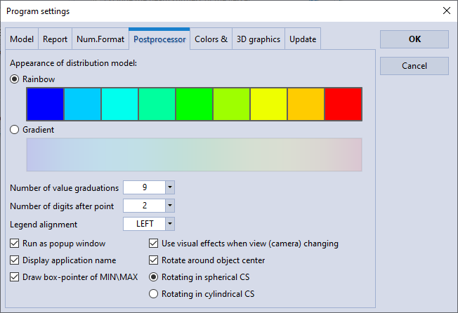 |
| Fig. 3.85. Postprocessor Parameters Customizing |
The main parameters are descibed below:
| Parameters | Description |
| Appearance of distribution model | Sets the method for the distribution displaying of value isofields (displacements, stresses, etc.). You can set one of two values for Isofield or Gradient. The first option is the default and displays the data distribution (scalar fields) in the form of subareas of the same color, the values of which in points fall into one division of the numerical color scale (hereinafter the color scale). The second option displays scalar fields in such a way that intermediate color values in graphic primitives are determined by interpolation, and color values in primitive nodes are determined by a color scale. |
| Number of value graduations | Specifies the number of color legend divisions that matches the displayed magnitude distribution (scalar field) of color values. For example, a specific color is assigned to each voltage value. |
| Number of significant digits after point | Specifies the number of digits for real value (float point) divisions to display on the color legend. |
| Legend alignment | Sets the color legend position relative to the postprocessor window borders. There are four possible positions: left, right, top and bottom. |
| Run as popup window | Allows you to run the post processor both in a separate default window and as a tab in the main window. |
| Display application name | Enables or disables the program name in the postprocessor window. |
| Draw box-pointer of MIN\MAX | Enables or disables the display of the pointer at the point where the minimum or maximum of the displayed value (scalar field) is detected. |
| Use visual effects when view (camera) changing | Enables or disables the display of auxiliary graphic objects that help to change the camera position of 3D scene (shift, rotate, enlarge, etc.). |
| Rotate around object center | Enables or disables rotation around the object center. When disabled, the rotation center becomes the point at which the camera (observer) is looking, located along a line perpendicular to the screen plane and passing through its center. |
| Rotating in spherical CS | Rotation in a spherical CS is a rotation around the center where the rotation arm ends on the point of the sphere that the mouse cursor is pointing to. |
| Rotating in cylindrical CS | Rotation in a cylindrical CS is a rotation around a center. When you move the mouse pointer in the horizontal direction of the screen, the object rotates around the vertical axis of the model. When you move the mouse pointer in the vertical direction of the screen, the object rotates in the plane where the vertical axis of the model lies, and perpendicular to the horizontal axis of the screen. |
PASS/NOZZLE-FEM 3.5. Program Manual
Copyright © 2017-2026, PASS Team