

|
PASS/NOZZLE-FEM 3.5. Program Manual | |
Dialog box for the results view allows you to interactively view the results, obtained during the calculation of the deflected mode due to action given the forces and pressure (fig. 3.80).
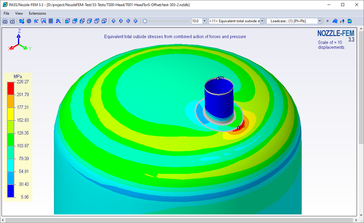 | |
| Fig. 3.80. Interactive interface the graphical representation of the calculation results | |
The window is opened by pressing the 3D button located under each drawing of the model, in the tab "Calculation results".
The main function of the postprocessor is to view the results of finite element analysis (FEA): displacements, stresses, and user-specified loads.
To view displacements or rotation angles at the structure points, select "Displacement..." item in the corresponding toolbar dropdown list, as shown in fig. 3.81.
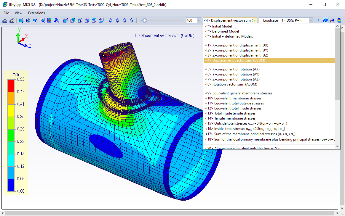 | |
| Fig. 3.81. Displaying the total displacement distribution | |
To view stresses at the structure points, select "Stress..." item in the corresponding toolbar dropdown list, as shown in fig. 3.82.
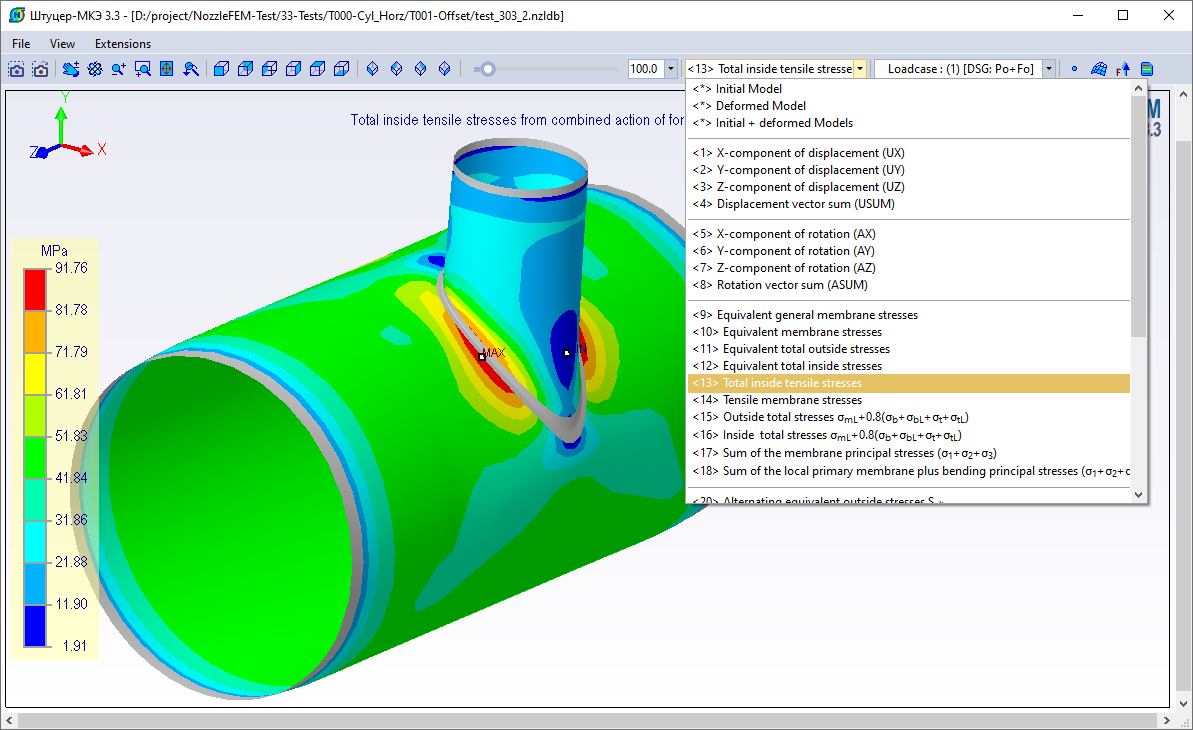 | |
| Fig. 3.82. Displaying the total tensile stress distribution | |
To view user defined loads, select one of the items in the corresponding toolbar dropdown list: surface or body forces. Surface forces (pressure) can be displayed as contours or arrows applied perpendicular to the loaded finite element surface (fig. 3.83).
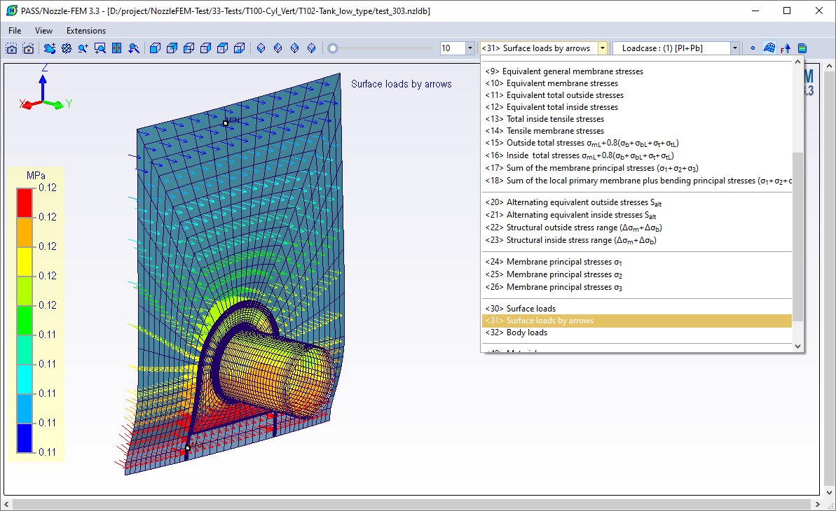 | |
| Fig. 3.83. Displaying the pressure distribution | |
Another way to display boundary conditions and loads is to use the toolbar command, which allows you to choose what to display as well as set display options (fig. 3.84).
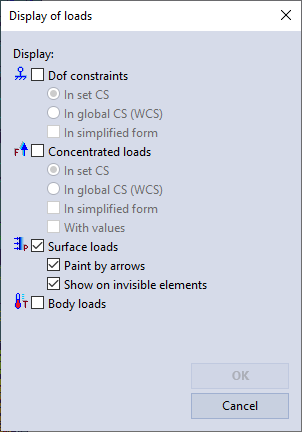 | |
| Fig. 3.84. Dialog box of parameters displaying loads | |
PASS/NOZZLE-FEM 3.5. Program Manual
Copyright © 2017-2026, PASS Team