

|
PASS/NOZZLE-FEM 3.5. Program Manual | |
Setting is provided by selecting the main menu item: Options/Settings,
or by pressing button  of main toolbar.
The first tab of the dialog box sets the orientation of the global (world) coordinate system (WCS), which is used to build a model and generate report figures (fig. 3.12).
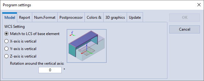 |
| Fig. 3.12. The model WCS settings |
| Parameter | Description |
| Match to LCS of base element | The WCS will correspond to the local coordinate system of the base element (see Base element setting). That is, the global vertical axis will coincide with the vertical local axis of the base element. This option follows the approach used in versions 3.3 and earlier. |
| X-axis is vertical | The model will be built with a vertical global X-axis. This option can be used, for example, when it is necessary that the vertical axis in the report images be the X-axis, regardless of the LCS orientation of the considered base element. |
| Y-axis is vertical | The model will be built with a vertical global Y-axis. This option can be used, for example, when it is necessary that the vertical axis in the report images be the Y-axis, regardless of the LCS orientation of the considered base element. |
| Z-axis is vertical | The model will be built with a vertical global Z-axis. This option can be used, for example, when it is necessary that the vertical axis in the report images be the Z-axis, regardless of the LCS orientation of the considered base element. |
| Rotation around the vertical axis | It allows you to override the orientation of the horizontal global axes. A positive angle value specifies counterclockwise rotation. This option can be used, for example, when it is necessary to coincide the WCS with the global CS of another program from which data (in particular, loads) is transferred, the recalculation of which may cause difficulties. |
In this tab of the dialog box, parameters are set that relate to the presentation of calculation results in the program report (fig. 3.13).
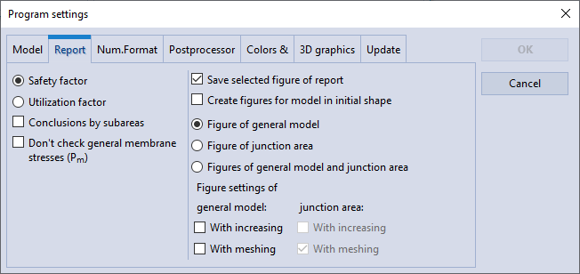 |
| Fig. 3.13. Report Settings Dialog Box |
The table below provides a description of the parameters:
| Parameter | Description |
| Safety factor | Specifies the output of the calculated minimum safety factor from all loadcase checks. The safety factor is calculated as the ratio of the allowable stress to the maximum calculated stress. If the safety factor is not less than 1.0, then the strength conditions are satisfied. |
| Utilization factor | Specifies the output of the calculated maximum utilization factor from all loadcase checks. The utilization factor is calculated as the ratio of the maximum calculated stress to the allowable stress, that is, it is the inverse of the safety factor. If the utilization factor is not more than 1.0, then the strength conditions are satisfied. |
| Conclusions by subareas | Sets the display mode of checks for all element subareas. Otherwise, most of the checks will be combined into one, which will lead to a shorter form of the report. |
| Don't check general membrane stresses (Pm) |
It allows you to exclude the check of general membrane stresses from the report and calculation of the safety factor (utilization factor). |
| Save selected figure of report | If the user changes the report picture using the control buttons (increase, zoom in, show grid, etc.),
then this report state will remain after the program is closed, and will also be valid when exporting to an RTF report. Otherwise, the last selected picture will not be saved, and the initially generated pictures will go to the RTF report. |
| Create figures for model in initial shape | When report is generated after calculation or by a separate command,
all pictures will be created in their initial undeformed state (the scale factor of displacements will be 0.0). Otherwise, the pictures will be created in a deformed state with the automatically calculated scaling factor of displacements. |
| Figure of general model | By default, report pictures will be created for the general model (as in the action of the control button increase). |
| Figure of junction area | By default, report pictures will be created for the junction area (as in the action of the control button zoom in). |
| Figures of general model and junction area | By default, two pictures will be displayed: the general model and the junction area. |
| Figure settings | Sets the default display options for general model and inset area images.
|
In this tab of the dialog box, parameters of floating-point number formats are set, which relate to the presentation of calculation results in reports and the user interface (fig. 3.14).
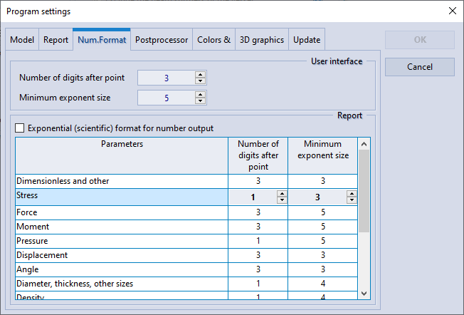 |
| Fig. 3.14. Number Format Settings Dialog Box |
The table below provides a description of the parameters:
| Parameter | Description |
| Number of significant digits | Specifies the maximum number of significant digits after the decimal point for output values. The option affects the display of values in user interface. |
| Minimum exponent size | Specifies the minimum order of a value beyond which the value is displayed in exponential form. The option affects the display of values in user interface. |
| Exponential (scientific) format for number output | Specifies the scientific format for outputting values: 1.23E+10. Otherwise, exponential values will be output as 1.23·1010. The option affects the display of values only in the report. |
| "Dimensionless and other", "Angle", "Displacement", "Diameter, thickness, other sizes", ..., "Linear stiffness", "Angular stiffness", "Linear flexibility", "Angular flexibility" |
It specifies the output format for value different categories: stresses, dimensions, etc. Each category has two parameters:
The option affects the output only in the report. |
This tab sets the parameters that control of data display in the preprocessor. The more detailed description is given in the section "Postprocessor Parameters Customizing".
This tab sets the color scheme of data display in the preprocessor. For more detailed description, see the section "Color Customizing".
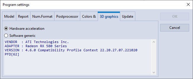
Program uses OpenGL to draw three-dimensional graphics.
The tab allows to enable/disable hardware acceleration of three-dimensional graphics (fig. 3.15). If hardware acceleration is enabled, information about the vendor and adaptor type, as well as the driver version, is displayed (fig. 3.15a). If hardware acceleration is disabled, then the software implementation of OpenGL is used (fig. 3.15b).
The software generic option can help in cases where an old adapter is used, for which the vendor no longer supports driver updates.
The change of modes is carried out only after program reboot.
 |
| a) |
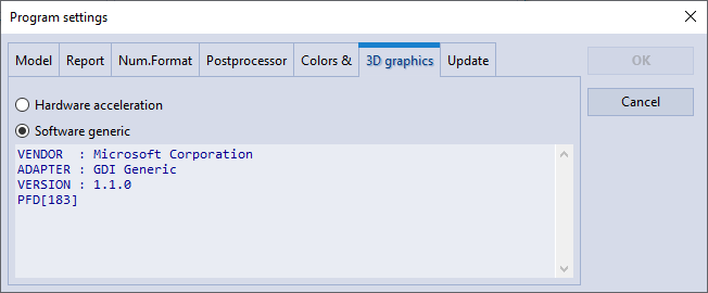 |
| b) |
| Fig. 3.15. 3D graphics setting |
The tab presents the update system (fig. 3.16) that can check for updates in automatic or manual mode, as well as download and install updates on PC.
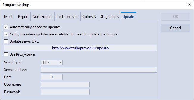 |
| Fig. 3.16. General Settings Dialog Box |
For the proper work of the system a dongle is required. If the dongle is not available, check and installation of updates cannot be performed.
Check for updates is performed automatically at the program launch, or manually from Help→Check for updates menu. Automatic check can be switched off in the parameter settings window, check button "Check for updates at each run".
Check and installation of updates is performed up to maximum allowed version number, which is specified in the dongle. Software update system can notify a user of the available updates to the latest versions, which are newer than those allowed by the dongle, if the following item is switched on: "Notify of updates, which require dongle updating" in the parameter settings window. If this message appears, such updates become available after the dongle update to the required version.
To install updates, system administrator's rights are required. There can be a request of UAC (Windows User Access Control system) about permission of install.exe launch during installation process. For proper updating, install.exe shall be launched with administrator's rights.
Proxy settings may be required for connecting to update server. The same proxy settings as in a web-browser should be set. In the case of Internet Explorer these settings can be found in the tab Connections→Network properties of the Internet Options.
PASS/NOZZLE-FEM 3.5. Program Manual
Copyright © 2017-2026, PASS Team