Results list window
This window displays the results of the steady-state flow calculation (isothermal flow calculation, diameters calculation or heat and hydraulic analysis). The name of the tab with the results in the list window corresponds to the type of calculation performed.
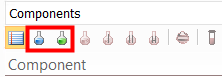
The results list window is synchronized with the Project Tree window, the Object Properties window, and other program windows - when you select an element in any of the windows, the focus moves to it in other program windows. At the top of this window there are toggle buttons that allow you to display results for different phases (for multiphase flows) and a drop-down list in which you can select which elements of the pipeline system to display results for. The results are most conveniently displayed in the following three presentation options:
This option allows to display the calculated parameters in summary form for each of the pipeline branches. To display results by branches, you must either select "Branches" in the drop-down list at the top of the results list window, or simply select the pipeline in the project tree. The following parameters are displayed in the results by branches:
|
Diameter |
Fluid flowrate |
Total length of the branch |
Maximum fluid velocity |
Maximum fluid density |
Pressure losses (due to friction, local losses, etc.) |
Initial and final pressure in the branch |
Initial and final temperature in the branch |
NPSH and saturation pressure |
Isothermal flow calculation and diameters calculation for liquid |
✔ |
✔ |
✔ |
✔ |
✔ |
✔ |
✔ |
|
✔3 |
Isothermal flow calculation and diameters calculation for gas |
✔ |
✔ |
✔ |
✔ |
✔ |
✔ |
✔ |
|
|
Heat and hydraulic calculation for liquid |
✔ |
✔ |
✔ |
✔ |
✔ |
✔ |
✔ |
✔ |
✔3 |
Heat and hydraulic calculation for gas |
✔ |
✔ |
✔ |
✔ |
✔ |
✔ |
✔ |
✔ |
|
Isothermal flow calculation and diameters calculation for gas-liquid flow |
✔ |
✔1 |
✔ |
✔1 |
✔1 |
✔ |
✔ |
|
|
Heat and hydraulic calculation for gas-liquid flow and flow with phase transitions |
✔ |
✔1 |
✔ |
✔1 |
✔1 |
✔ |
✔ |
✔ |
|
Isothermal flow calculation for "three-phase" flow |
✔ |
✔ |
✔ |
✔ |
✔ |
✔ |
|
|
|
Heat and hydraulic calculation for "three-phase" flow |
✔ |
✔ |
✔ |
✔ |
✔ |
✔ |
✔ |
|
|
Isothermal flow calculation for liquid flow with solid phase |
✔ |
✔ |
✔ |
✔ |
✔ |
✔ |
✔ |
|
✔3 |
Heat and hydraulic calculation for liquid flow with solid phase |
✔ |
✔ |
✔ |
✔ |
✔ |
✔ |
✔ |
✔ |
✔3 |
________________________________________________
1 - For gas-liquid
flows (including mixtures of two liquids with gas), the total flow rate
and average velocities and densities of the gas-liquid mixture are displayed
in the general calculation results. In addition, you can view the parameters
of the gas and liquid phases separately. To do this, select any of the
branches and click the button  in the upper left part of the results
list window to view data for the gas phase or the button
in the upper left part of the results
list window to view data for the gas phase or the button  to view data
for the liquid phase:
to view data
for the liquid phase:

To
return to the general calculation results, click the button  . Please note that the gas and liquid
phase flow rates in the flow are displayed only when using the "frozen"
flow model (when each phase in the flow is specified as a separate fluid
and the mass transfer between the phases is assumed to be negligible).
For flows with mass transfer between the phases, the phase flow rates
are not displayed in the calculation results, since they change along
the flow during the boiling/condensation of the fluid and can be different
in the same branch.
. Please note that the gas and liquid
phase flow rates in the flow are displayed only when using the "frozen"
flow model (when each phase in the flow is specified as a separate fluid
and the mass transfer between the phases is assumed to be negligible).
For flows with mass transfer between the phases, the phase flow rates
are not displayed in the calculation results, since they change along
the flow during the boiling/condensation of the fluid and can be different
in the same branch.
2 - For three-phase flows, the water cut and gas factor of the flow are also displayed.
3 - By default, the NPSH and the bubble point pressure of the liquid are not calculated and are not output in the calculation results. To calculate and output them, it is necessary to turn on the "Calculate NPSH" option in the input data for those branches for which these values are of interest.
If different fluids with different
compositions are specified for branches in the pipeline, then when presenting
results by branches, by clicking on the corresponding button in the upper
left part of the results list window, you can view the fluids compositions
in each of the branches (to view the gas and liquid compositions of a
two-phase fluid, after clicking on the "Components, %" button,
click on the button in the
upper left part of the results list window to view the composition of
the gas phase or the button
for the composition of the liquid phase):
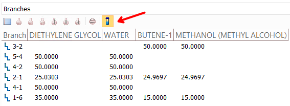
Compositions are displayed in the same units (mol or mass %) that were used when specifying the fluid compositions.
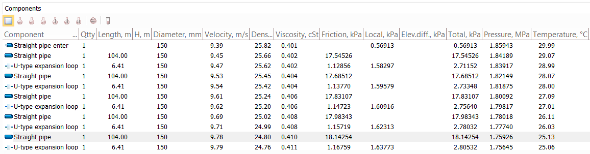
Results by components (resistances)
This option allows to display the calculated parameters in more detail for each individual pipeline element (pipe, bend, etc.). To display the results by sections, select the pipeline element; the window will display the results for this and all other sections of this branch. The following parameters are output in the resistance results:
|
Fluid velocity |
Fluid density |
Fluid viscosity |
Fluid phases ratio6 |
Pressure losses (due to friction, local losses, etc.) |
Pressure |
Temperature |
Heat loss |
NPSH |
Mach number |
Reynolds number |
Flow pattern |
Elevation |
Isothermal flow calculation and diameters calculation for liquid |
✔ |
✔ |
✔ |
|
✔ |
✔ |
|
✔7 |
|
✔ |
|
✔ |
|
Isothermal flow calculation and diameters calculation for gas |
✔ |
✔ |
✔ |
|
✔ |
✔ |
|
|
✔ |
✔ |
|
✔ |
|
Heat and hydraulic calculation for liquid |
✔ |
✔ |
✔ |
|
✔ |
✔ |
✔ |
✔ |
✔7 |
|
✔ |
|
✔ |
Heat and hydraulic calculation for gas |
✔ |
✔ |
✔ |
|
✔ |
✔ |
✔ |
✔ |
|
✔ |
✔ |
|
✔ |
Isothermal flow calculation and diameters calculation for gas-liquid flow |
✔4 |
✔4 |
✔4 |
✔ |
✔ |
✔ |
|
|
✔ |
✔ |
✔ |
✔ |
|
Heat and hydraulic calculation for gas-liquid flow and flow with phase transitions |
✔4 |
✔4 |
✔4 |
✔ |
✔ |
✔ |
✔ |
✔ |
|
✔ |
✔ |
✔ |
✔ |
Isothermal flow calculation for "three-phase" flow |
✔4 |
✔4 |
✔4 |
✔ |
✔ |
✔ |
|
|
✔ |
✔ |
✔ |
✔ |
|
Heat and hydraulic calculation for "three-phase" flow |
✔4 |
✔4 |
✔4 |
✔ |
✔ |
✔ |
✔ |
✔ |
|
✔ |
✔ |
✔ |
✔ |
Isothermal flow calculation for liquid flow with solid phase |
✔5 |
✔5 |
✔5 |
✔ |
✔ |
✔ |
|
|
|
✔ |
✔ |
✔ |
|
Heat and hydraulic calculation for liquid flow with solid phase |
✔5 |
✔5 |
✔5 |
✔ |
✔ |
✔ |
✔ |
✔ |
|
|
✔ |
✔ |
✔ |
Also in the results list for convenience, for each element its length, diameter, height differences and quantity are indicated.
Please note that the flow parameters (pressure, velocity, temperature, etc.) opposite each element in the results list are specified after the element. The first empty line in the results list for the components displays the flow parameters (pressure, velocity, temperature) before the first component (i.e., at the starting point of the branch).
________________________________________________
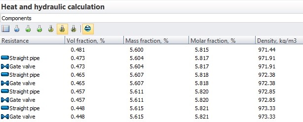
4 - For gas-liquid
flows (including mixtures of two liquids with gas), the average velocities,
densities and viscosities of the gas-liquid mixture are displayed in the
general calculation results. In addition, you can view the parameters
of the gas and liquid phases separately. To do this, click the button in the upper
left part of the results list window to view data for the gas phase or
the button to
view data for the liquid phase:
To
return to the general calculation results, click the button .
5 - For flows of mixtures of liquids with a solid phase, only the average velocity and properties of the mixture are output; the parameters of the liquid and solid phases are not output separately in the results.
6 - For gas-liquid flows (including mixtures of two liquids with gas), the ratio of the vapor and liquid phase in the flow is indicated in the form of the mass and volume fraction of gas, for mixtures of liquid with a solid phase - in the form of the mass and volume fraction of solid particles.
7 - The NPSH is displayed only for pumps (if any in the given branch) and only if the calculation of the NPSH calculation was enabled in the input data for the given branch. In this case, the results display both the actual NPSH at the pump inlet and the minimum NPSH required for the pump, if a NPSH curve was specified in the pump characteristics.
If the calculation of hydrate prediction using PVTSim was enabled for the pipeline in the calculation settings, then the results for hydrates and water phase will also be available in the list of calculation results for components:
They are enabled by clicking the "Phases by PVTSim" button at the top of the list window when viewing results for piping components. They include data on the following phases:
–
gas phase;
– liquid
(hydrocarbon) phase;
 – liquid water phase;
 – hydrates
with structure I;
– hydrates
with structure I;
 – hydrates with structure II;
 – hydrates with structure H (hexagonal).
For each phase (if present in the mixture) molar, volume and mass fraction as well as its thermo-physical properties (density, heat capacity etc.) are shown.
This option allows to display the calculated parameters for pipeline nodes. To display results by nodes, select "Nodes" in the drop-down list at the top of the results list window. Please note that if a branch or some element of a branch is currently selected, the results will be displayed only for the start and end node of this branch. To display results for all pipeline nodes, select the pipeline in the project tree. The following parameters are displayed in the results by nodes:
|
Node name |
Node number |
Number of branches connected |
Pressure in the node |
Inflow/outflow at a node |
Elevation of node |
Temperature |
Isothermal flow calculation and diameters calculation for liquid |
✔ |
✔ |
✔ |
✔ |
✔ |
✔ |
|
Isothermal flow calculation and diameters calculation for gas |
✔ |
✔ |
✔ |
✔ |
✔ |
✔ |
|
Heat and hydraulic calculation for liquid |
✔ |
✔ |
✔ |
✔ |
✔ |
✔ |
✔ |
Heat and hydraulic calculation for gas |
✔ |
✔ |
✔ |
✔ |
✔ |
✔ |
✔ |
Isothermal flow calculation and diameters calculation for gas-liquid flow |
✔ |
✔ |
✔ |
✔ |
✔ |
✔ |
|
Heat and hydraulic calculation for gas-liquid flow and flow with phase transitions |
✔ |
✔ |
✔ |
✔ |
✔ |
✔ |
✔ |
Isothermal flow calculation for "three-phase" flow |
✔ |
✔ |
✔ |
✔ |
✔ |
✔ |
|
Heat and hydraulic calculation for "three-phase" flow |
✔ |
✔ |
✔ |
✔ |
✔ |
✔ |
✔ |
Isothermal flow calculation for liquid flow with solid phase |
✔ |
✔ |
✔ |
✔ |
✔ |
✔ |
|
Heat and hydraulic calculation for liquid flow with solid phase |
✔ |
✔ |
✔ |
✔ |
✔ |
✔ |
✔ |
Please note that if any changes are made in the input data, the calculation results are immediately reset.