Pump
To add a new pump,
click the button  of Components
toolbar
and select the equipment type "Pump"
(or
use the corresponding item of "Insert
- Component - Equipment"
menu). Please note that
the new component is added to the project tree after the currently selected
element. Therefore, to add a new component after an existing one, select
it in the project tree or in the graphic window and add the new component.
If you need to add a new component to the beginning of a branch, select
the branch in the project tree and add the new component.
of Components
toolbar
and select the equipment type "Pump"
(or
use the corresponding item of "Insert
- Component - Equipment"
menu). Please note that
the new component is added to the project tree after the currently selected
element. Therefore, to add a new component after an existing one, select
it in the project tree or in the graphic window and add the new component.
If you need to add a new component to the beginning of a branch, select
the branch in the project tree and add the new component.
The pump element is used to
model the operation of centrifugal pumps with
known characteristics on a pipeline system and to determine
the pump operating point. Note that if the pump operating point is initially
known (for example, the flow through the pump is controlled by a control
valve and the pump head is known for this flowrate), then it is not necessary
to specify the "Pump" element in this case (unless you plan
to perform a waterhammer calculation). In this case, the pump can be modeled
as a "Component
with known change of pressure and/or temperature", for which
the pump head can be specified manually. Or, if the pump is at the starting
point of the piping system, you can simply specify the pressure at the
pump outlet as the initial pressure in this system, without modeling the
pump itself.
If the purpose of your calculation
is to select a pump,
then you do not need to specify the "Pump" element for this.
Pump selection is performed in a different way - see below for
more details .
After
adding a pump, its characteristics
will be displayed in the Object Properties Window:
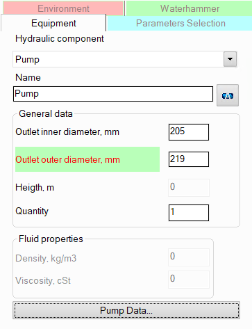
name -
by default, the name of any piping component coincides with its type,
but if necessary, the name can be changed in this field. When changing
the hydraulic component type (when selecting different types of equipment),
its name will also change, but only if it has not been previously
changed to another manually. Specify the name that you would like
to see for this element in reports with calculation results. To display
the name of a pipeline element on the diagram, click the corresponding
button to the right of its name;
pump outlet
diameters (inner and outer) - by default they are taken to
be equal to the diameters of the pump inlet (i.e., diameter of the
component before the pump). If necessary, they can be changed in these
fields. The specified values
of the new
inner and outer diameters after the
pump are applied to
all components of
the branch after this component
until the end of
the branch or until the next component
with a diameter
change (if there is one in this branch). Please note that when adding
and deleting pumps,
as well as when changing their new diameter value, the program will
not only automatically adjust the values of the diameters of all the
following components in this branch (up to the first element with
a change in diameter if any),
but will also change the values of the radii of the bends and elbows
in this branch if they are equal to the standard value of 1.5*DN (for
pipes with DN < 500mm) or 1*DN (for pipes with DN >=
500mm);
quantity -
this parameter is usually not used for pumps. It is used for other
pipeline elements (for example, for valves) when modeling several
identical elements. In this case, you can enter the number of these
elements in this field and when calculating the hydraulic resistance
on this element will be multiplied by the specified value. Since there
are unlikely to be several identical pumps installed in series in
one pipeline branch, this option is of no practical interest for it;
control type/performance
curve/manufacturer - these parameters
are filled in "for reference", they are not required
for calculations and preparation of reports with results;
pump head vs. flow rate curve is
the main characteristic of the pump, which determines its operation
on a given pipeline system. It must be specified for the pump;
pump
NPSH vs. flow rate curve - this characteristic is
required only if you plan to calculate the required NPSH at the
pump operating point. Otherwise, it can be omitted;
range of operation limits -
here you can specify the boundaries of the preferred working zone
of the pump. If the calculation shows that the pump's working
point is outside this zone, the program will show a corresponding
warning. If the boundaries are not specified, this diagnostic
will not be performed. The working zone boundaries are displayed
as a blue rectangle on the graph;
pump impeller rotational
speed - important at the waterhammer calculation and for
viscosity correction calculation (see below);
diameter of
the pump impeller - required only when calculating the flows of
liquids containing a solid phase, since the correction of the
pump characteristics by the solid phase depends on the diameter
of the pump impeller. For liquids, this parameter can be omitted;
viscosity correction is factored
into performance curve - when calculating
the pumping of viscous liquids (with a viscosity over 4 cSt),
the program automatically recalculates the pump head curve by
viscosity according to the ANSI/HI method. However, if this correction
is already taken into account in the pump head curve (for example,
the pump manufacturer provided data on the pump's operation on
a viscous liquid), then it is necessary to disable this recalculation
by enabling this option. If this option is disabled, the recalculation
by viscosity will be performed.
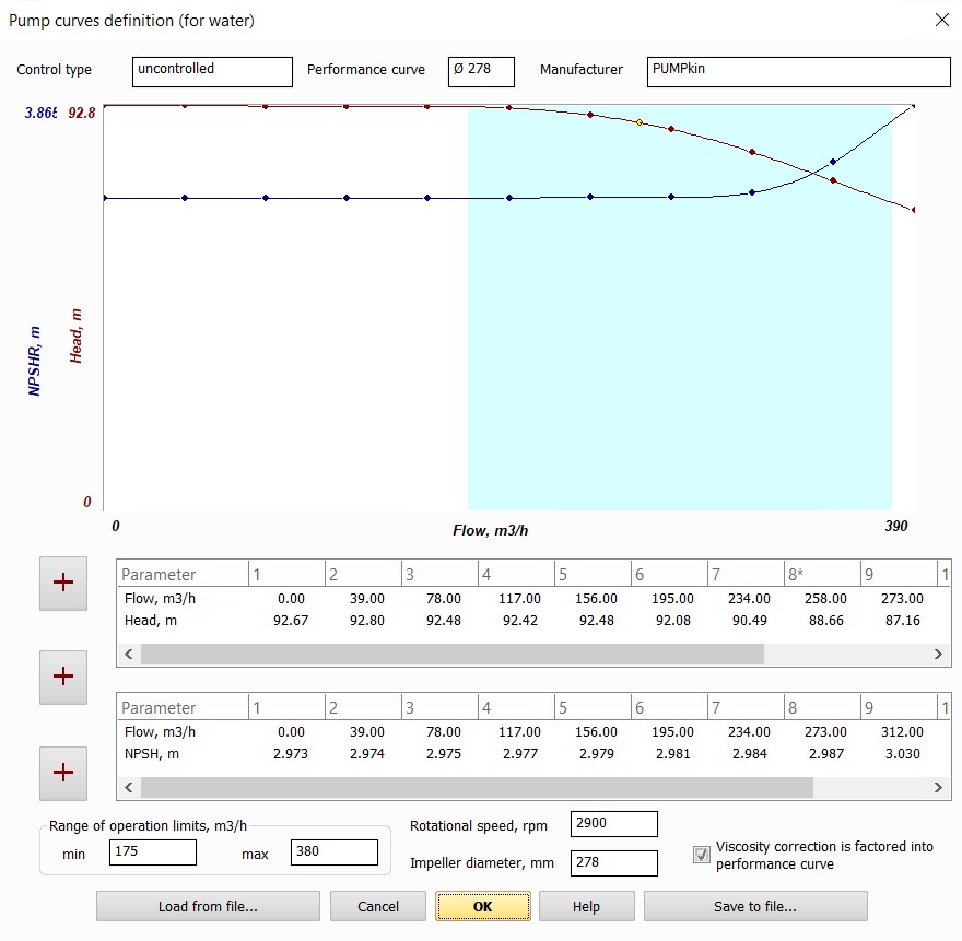
Pump
curves are set point-by-point; buttons  to
the left of the tables are used to add points to the tables:
to
the left of the tables are used to add points to the tables:
the
top button adds a new point to the table of the head curve;
the lower one – to the table of the NPSH
curve;
central – in both tables simultaneously.
The graphs of the pump head and
net positive suction head dependencies on the flow rate are displayed
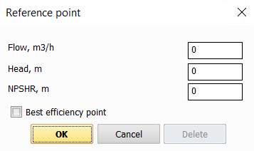
as the control points are filled. The
control points are written to the tables in ascending order of the flow
rate value. To edit a point already specified in the table,
right-click on the value you want to edit and select Edit. However,
please note that you can only change the head or NPSH value in this way.
Editing the flow rate value for a point is not available, so if you need
to change the flow rate, you should delete
the existing point and enter a new one in its place. To delete a point, right-click
on it in the table (on the value in the table, not the point number) and select Delete.
One
of the points of the pump head curve must be specified as the Best efficiency point
(the point with the maximum pump efficiency) by checking the corresponding
box while adding the point. On the graph, such a point is marked in yellow,
and in the table - with an asterisk next to its number.
All the
above pump characteristics can usually be found in pump passport data.
For a more accurate approximation of pump curves, it is recommended to
specify a large number of reference points (at least 3, but more is better).
It is not allowed to specify pump characteristics consisting of only one
point. If the pump passport does not include pump head vs. flow data,
but indicates only, for example, the value of the nominal head/pressure
and flow of the pump, in such cases, instead of the "Pump" element,
it is recommended to use "Component
with known change of pressure and/or temperature", for which
the pump pressure difference can be specified manually.
The entered pump characteristics
can be saved in a file with the .pmp
extension for
subsequent use in other pumps. To do this, use the
Save to file and Load
from file buttons.
Please note that from a hydraulic
point of view, a pump is considered as a "point" (or "concentrated")
resistance that has no length/width/height. Therefore, if it is necessary
to take into account the pump dimensions in a diagram, they can be modeled
as a pipe with the corresponding length and orientation in space. However,
there is little practical interest in this, since, as a rule, the pump
pressure value already includes pressure losses inside the pump and the
hydrostatic drop on it. Therefore, it may be necessary to model the pump
dimensions only in cases where the pump is located in a closed loop
(so that the piping model looks correctly,
without gaps).
Pump selection using Spaix
To select a pump in the Hydrosystem,
it must be modeled as "Component
with known change of pressure and/or temperature" with pressure
drop equal to the required pump head (please note that this pressure drop
in this case is specified with a minus sign since it should model the
increasing of pressure). The required pump head must be pre-determined
by calculation (for more information on such calculation, see here).
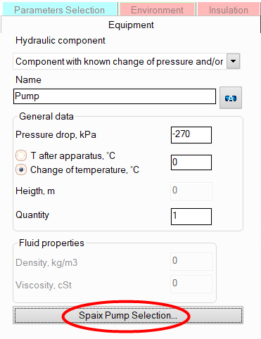
It
is necessary to perform a calculation (isothermal or heat analysis) for
this pipeline, after which in the Object Properties Window for this component
the button "Spaix Pump Selection…"
will appear, when clicked, the application "Spaix 4 Pumps" (if
installed on the computer) will be launched to select the pump. All the
information necessary for selecting the pump (required pressure, flow,
properties of the pumped fluid, etc.) will be automatically transferred
to Spaix:
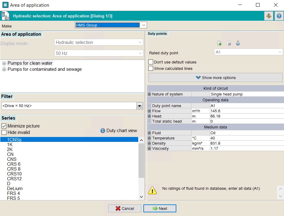
In
Spaix, the user will need to select the manufacturer and the preferred
pump type, after which, by clicking the Next button, all suitable
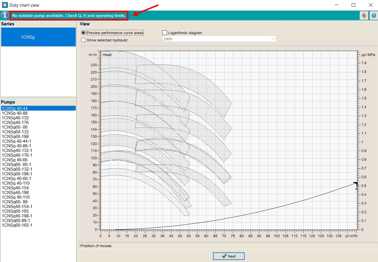
pumps of this type will be shown. If there are no suitable pumps for the
given conditions in this category, Spaix will inform you about this in
the corresponding window (in this case, click the Next button to return
to the choice of manufacturer and pump type):
If
there are suitable pumps, their list with basic characteristics will be
displayed in the corresponding window:
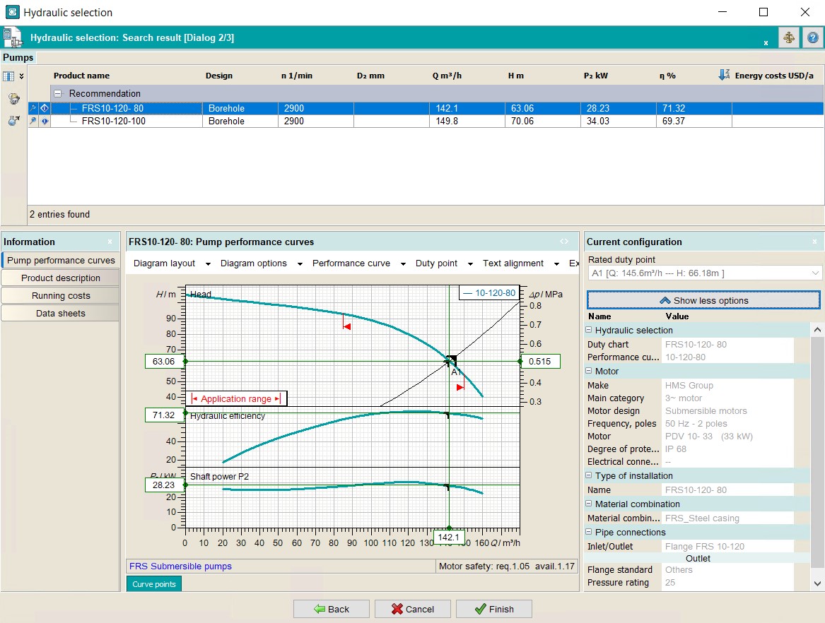
Here you need to select the desired
pump and, if necessary, adjust its configuration parameters. After confirming
the pump selection in Spaix, its parameters (head and NPSH curves, range
of operation limits, rotational speed, etc.) will be transferred to the
Hydrosystem. This component with known change of pressure and/or temperature
will be converted to a pump element and the pipeline will be recalculated
with the selected pump. To cancel the pump selection and return to the
original component with known change of pressure and/or temperature, use
the Cancel command in the Edit menu or Edit
toolbar.
For
more detailed information on how Spaix 4 Pumps works, please refer to
the documentation/help for this software.