Orifice
To add
a new orifice, click the button  of Components toolbar
or use the corresponding item of "Insert
- Component" menu. Please note that the new component
is added to the project tree after the currently selected element. Therefore,
to add a new component after an existing one, select it in the project
tree or in the graphic window and add the new component. If you need to
add a new component to the beginning of a branch, select the branch in
the project tree and add the new component.
of Components toolbar
or use the corresponding item of "Insert
- Component" menu. Please note that the new component
is added to the project tree after the currently selected element. Therefore,
to add a new component after an existing one, select it in the project
tree or in the graphic window and add the new component. If you need to
add a new component to the beginning of a branch, select the branch in
the project tree and add the new component.
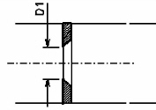
The orifice element is used to model the hydraulic resistance that occurs when the flow is narrowed and then expanded in orifice plates with sharp edges, and also to calculate the required diameter of the orifice to control various flow parameters (pressure, flow rate, etc.).
After adding the orifice, its characteristics will be displayed in the Object Properties Window:
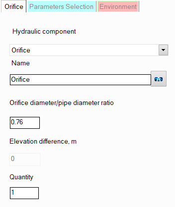
name - by default, when entering a new piping component, its name matches the type, but if necessary, it can be changed in this field. Specify the name that you would like to see for this component in reports with calculation results. To display the component name on the piping diagram, click the corresponding button to the right of its name;
orifice diameter to pipe diameter ratio - in this field you must enter the ratio of the orifice diameter to the internal diameter of the pipe;
quantity - this parameter is used in cases when it is necessary to simulate and calculate the resistance of several identical orifices without specifying each of them separately. To do this, you need to specify the number of such orifices in this field, and at the calculation, the hydraulic resistance on this element will be multiplied by the specified value. Of course, not all orifices will be displayed on the graphical diagram (only one of them will be displayed), but they will be taken into account in the calculation. However, it is important to note that this method of setting not always gives a good accuracy of calculation, since it does not take into account that a change in pressure and temperature after the next piping component may entail a change in the density and viscosity of the fluid (which is especially crucial for gases and gas-liquid mixtures), and, consequently, a change in the pressure drop on subsequent elements. This method can be used for a quick rough estimate and mainly for liquids, the properties of which don't change (for instance, at a constant temperature) or change slightly along the pipeline. For a more accurate calculation, you should specify all components sequentially in the exact order they appear (even if there are repeating ones among them).
If the purpose of your calculation is to calculate the orifice/throttle plate diameter required to control pressure, flow or other flow parameter, see here for more information on such calculations.
Please note that from a hydraulic point of view, the orifice is considered as a "point" (or "concentrated") resistance that has no length.