Compensator
(expansion joint or loop)
To add
a new compensator (expansion joint or loop),
click the button  of Components
toolbar
or use the corresponding item of "Insert
- Component" menu. Please note that the new component
is added to the project tree after the currently selected element. Therefore,
to add a new component after an existing one, select it in the project
tree or in the graphic window and add the new component. If you need to
add a new component to the beginning of a branch, select the branch in
the project tree and add the new component.
of Components
toolbar
or use the corresponding item of "Insert
- Component" menu. Please note that the new component
is added to the project tree after the currently selected element. Therefore,
to add a new component after an existing one, select it in the project
tree or in the graphic window and add the new component. If you need to
add a new component to the beginning of a branch, select the branch in
the project tree and add the new component.
After
adding a compensator, its
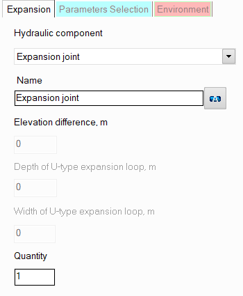
characteristics will be displayed in the Object Properties Window:

|
Bellows
or lens expansion joint |
No additional parameters need
to be set for this type of compensator. |
|
U-type
expansion loop |
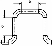
As additional
parameters for this type of compensator, it is necessary to specify
the depth a and the
width b of the
compensator. The U-shaped
compensator is calculated by the program as
a sequence of 4 90° elbows and 3 straight pipes (2 sections
with length a and 1
section with length b - see
the figure on the left). The radii of the bends are taken equal
to:
R=1.5·DN at DN <500, R=DN at DN >=500 |
name -
by default, the name of any piping component coincides with its type,
but if necessary, the name can be changed in this field. When changing
the hydraulic component type (when selecting different types of compensators),
its name will also change, but only if it has not been previously
changed to another manually. Specify the name that you would like
to see for this element in reports with calculation results. To display
the name of a pipeline element on the diagram, click the corresponding
button to the right of its name;
quantity -
this parameter is used in cases when it is necessary to simulate and
calculate the resistance and heat losses of several compensators of
the same type, without specifying each of them separately. To do this,
enter the number of such compensators in this field, and during the
calculation, the hydraulic resistances and heat losses on this compensator
will be multiplied by the specified value. Of course, not all compensators
will be displayed on the graphical diagram (only one of them will
be displayed), but they will be taken into account in the calculation.
However, it is important to note that
this method of setting not always gives a good accuracy of calculation,
since it does not take into account that a change in pressure and
temperature after the next piping component may entail a change in
the density and viscosity of the fluid (which is especially crucial
for gases and gas-liquid mixtures), and, consequently, a change in
the pressure drop on subsequent elements. This method can be used
for a quick rough estimate and mainly for liquids, the properties
of which don't change (for instance, at a constant temperature) or
change slightly along the pipeline. For a more accurate calculation,
you should specify all components sequentially in the exact order
they appear (even if there are repeating ones among them);
Please note that from a hydraulic
point of view, a lens
expansion joint is considered as a "point" (or "concentrated")
resistance that has no length. Therefore, if it is necessary to take into
account the dimensions of such a compensator in the calculation (to calculate
and account for the friction losses, heat losses and hydrostatic pressure
drop that occur on it), they can be modeled separately as a piece of pipe
with the corresponding length, or the length of the compensator can be
added to the lengths of the pipes adjacent to the compensator. However,
this only makes sense in cases where the expansion joint:
has really large size
that cannot be neglected;
is located in a vertical or inclined plane
relative to the vertical - in this case, it is important to take into
account the hydrostatic pressure drop that occurs on it;
is located in a closed loop (so that the
piping model looks correctly, without gaps).
In other cases, friction losses on
the bellows/lens expansion joint (and therefore its length) are usually
neglected.
As for the
U-type expansion loop, from a hydraulic point of view it is considered
as a "dimensional" resistance (i.e., having a length). This
must be taken into account when specifying the pipes adjacent to it, indicating
their actual lengths
as the dimensions of these pipes (for more information, see here).
The total length of the compensator (taking into account the pipes and
the lengths of the bend arcs) will be displayed in the calculation results.
When
drawing a U-type compensator on a pipeline graphic diagram, the direction
of its extension is determined by the program arbitrarily and cannot be
changed. However, it should be noted that this not affects the calculation
results.