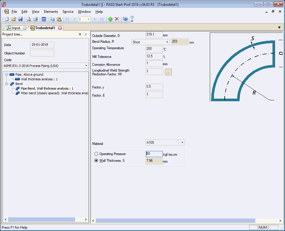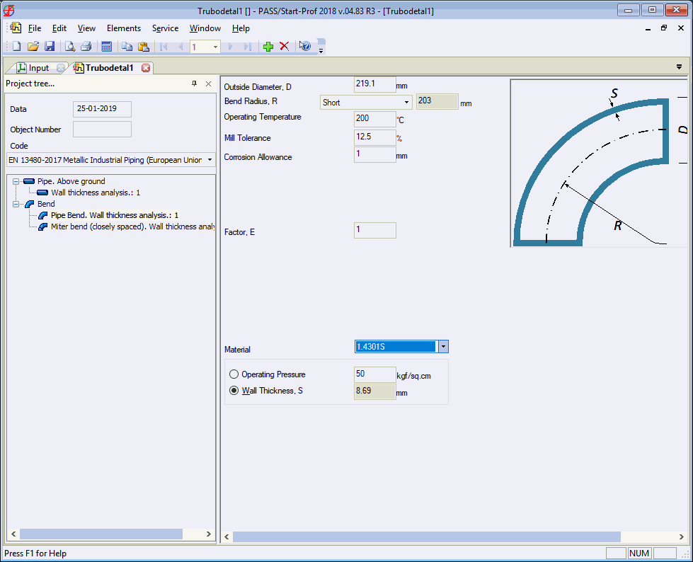

Calculates maximum allowable pressure for a given bend wall thickness, or minimum wall thickness for a given pressure. Also computes stress intensification factors (in-plane and out-of-plane) and maximum allowable bending moment. Bending moment calculations consider both static and fatigue failure criteria.


Copy input data using  toolbar
icon and paste into other Start-Elements analyses using
  toolbar icon.
Transfer bend properties between START-PROF and Start-Elements. More...
Property |
Description |
Mill tolerance |
Manufacturing wall thickness tolerance. More... |
Corrosion and wear allowance |
Corrosion/erosion allowance for wall thickness. More... |
Do not check internal bend wall thickness |
Per RD 10-249-98 section 3.3.2.8,
for extruded elbows or induction bends with axial preload,
set c12 allowance
from 0.05s to 0.1s for extrados (sR1) and 0 for
intrados (sR3). Internal bend analysis is omitted. |
Weld pressure quality factor |
Set per applicable standards.
Calculate automatically
using |
Weld bending quality factor |
Set per applicable standards.
Calculate automatically
using |
Ambient temperature |
Ambient installation temperature. More... |
Operation temperature |
Operating temperature in operating condition. More... |
Operation pressure, P |
Operating pressure in operating condition. Required for all standards except SNIP 2.05.06-85. More... |
Working pressure, Pwork |
Working pressure (standard-based calculation). Used for analysis with SNIP 2.05.06-85. More... |
Service life |
Piping design life (1-30 years). Used for fatigue analysis. |
Fatigue factor |
Used for fatigue analysis. Default: 1.0. Use lower values (0.2, 0.15, 0.1) for higher safety requirements. |
Steel grade |
Pipe material from materials database |
Select "pressure" to calculate allowable pressure for given wall thickness. Select "wall thickness" to calculate minimum wall thickness for given pressure.
Wall thickness must meet minimum requirements per:
SNIP 2.05.06-85 section 8.22
RD 10-249-98 section 3.3.1.3, table 3.3
GOST 32569-2013
GOST 32388-2013 table 1.3
For SNIP 2.05.06-85, additional wall thickness check per formula (66), section 13.16.
Wall thickness rounds up to 0.1 mm.