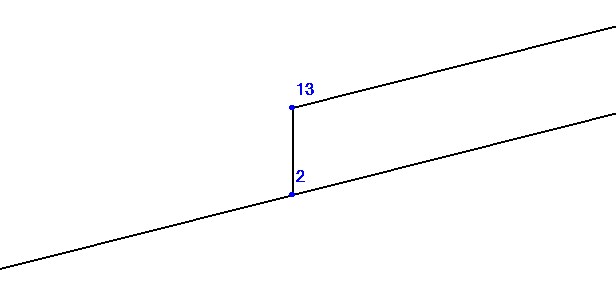

Learn about START-PROF pipe stress analysis software
Example project file: JacketedPipe.ctp
Jacketed piping systems require specialized stress analysis approaches.

Common jacketed piping applications:
Standard jacketed pipe configuration consists of concentric double-walled pipe with spacing components.
Spacers maintain annular gap between core and jacket pipes.
Partition plates manage heating medium flow distribution.

Typical jacketed pipe arrangement for viscous fluid heating
1 – core pipe, 2 – jacket pipe, 3 – flange pair, 4 - bypass piping
Model jacketed systems as parallel inner and outer pipes connected by jumper elements.
Pipe centerlines run parallel with minimal eccentricity (1-2 mm).

Jacketed piping analytical model
1- jacket pipe, 2 – core pipe, 3 – jumper element, 4 – anchor point
All external supports attach to jacket pipe.
Reduce jacket fluid weight by core pipe displacement volume.
Apply actual jacket operating pressure.
Include insulation weight on jacket pipe only.
Apply wind loads exclusively to jacket pipe.
Set core pressure as differential between internal and jacket pressures.
Exclude insulation weight from core pipe.
Apply actual product weight to core pipe.
Model spiders as specialized jumper connections.
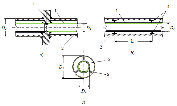
Jacketed pipe component details
a – flange connection; b – spider support; c – spider detail
1- jacket pipe, 2 – core pipe, 3 – flange pair, 4 – spider supports
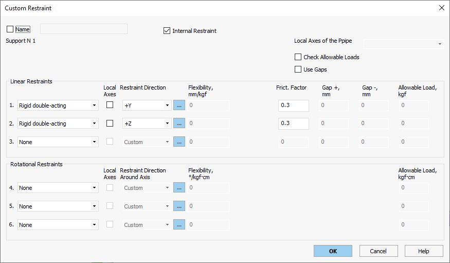
Jumper elements utilize rigid elements with internal restraints.
Internal restraints permit axial sliding between core and jacket pipes.
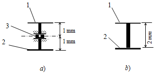
Jumper configuration types
a – spider jumper; b – flange jumper
1- jacket pipe, 2 – core pipe, 3 - custom expansion joint
Jumper element specifications:
Minimal length (2 mm) to limit eccentricity effects
Wall thickness equal to half tie rod diameter
Zero operating pressure
Minimal test pressure (1e-5 kgf/cm²)
Ambient temperature setting
Negligible weight (1e-5 kgf/cm)
Zero insulation and fluid weight
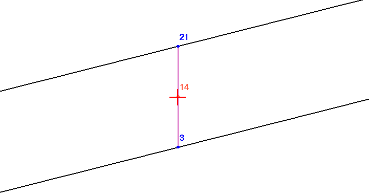

Flange pair jumpers follow similar modeling without expansion joints.
