

|
PASS/NOZZLE-FEM 3.5. Program Manual | |
Table 3.4 shows key features of the base element (shell).
| Table 3.4 | |
 | |
| Feature | Description |
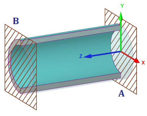
| Reference points: | A: shell start; B: shell end; |
| Local shell coordinate system (LCS): | Axis X: shell transverse axis; Axis Y: shell transverse axis; angle θ of nozzle insertion is taken from this axis toward axis X; Axis Z: shell longitudinal axis. |
| Orientation in WCS: | Axis Z is located in horizontal plane. Axis X and Y can be vertical according to the shell options: 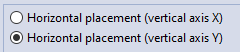 |
| Shell constraints (dof): | Points A, B. All calculations by the finite element method (FEM) fix both ends. |
| Shell loads: | Inner overpressure. Outer pressure. Hydrostatic pressure. Thermal strains. |
PASS/NOZZLE-FEM 3.5. Program Manual
Copyright © 2017-2026, PASS Team