 of Components toolbar
(or use the corresponding item in the
"Insert"
menu). If the selected node already contains a tee, it must be removed
first.
of Components toolbar
(or use the corresponding item in the
"Insert"
menu). If the selected node already contains a tee, it must be removed
first.Steam trap
To add a steam trap,
select the node into which you want to insert the steam trap on the Graphic
window or in the Data List Window (by enabling the Node view in the drop-down
list at the top of this window) and click the button of Components toolbar
(or use the corresponding item in the
"Insert"
menu). If the selected node already contains a tee, it must be removed
first.
The steam trap component is used to model condensate drainage from a two-phase gas-liquid flow at a given point in the pipeline. At the moment, the program implements a somewhat simplified condensate drainage model, namely:
1) at the calculation, it is assumed that the condensate is completely drained through the steam trap, and the vapor phase does not flow through the steam trap - i.e., if the node in which the steam trap is specified is supplied by:
two-phase mixture with a gas content greater than 0 but less than 1, then it is considered that after the steam trap, only the vapor phase remains in the flow (gas content = 1) with a flow rate equal to the initial flow rate (at the inlet to the steam trap) minus the flow rate of the formed condensate;
gas phase (with gas content equal to 1), then the steam trap has no effect on the flow - the flow rate and gas content of the flow after the steam trap remain the same as before it;
liquid phase (with gas content equal to 0), then the calculation is interrupted with an error, since in this case there is no fluid flow after the steam trap at all.
2) the hydraulic resistance of the steam trap at the flow passing through and condensate drainage is not taken into account in the calculation;
3) the condensate drainage line is not calculated.
By default, all the steam trap legs are assigned the standard names "Steam trap". However, if necessary, these names can be changed in the corresponding field. If the user changes this name, it will become the same for all branches of the specified steam trap.
Unlike all other piping components, a steam trap is added as two separate elements - steam trap niches (or legs). It is important to understand that this is a conventional name - it refers to the niches of the pipeline branching at the place of installation of condensate drainage devices. After inserting a steam trap, both niches will be added to the corresponding pipeline branch and their characteristics will be displayed in the Object Properties Window:
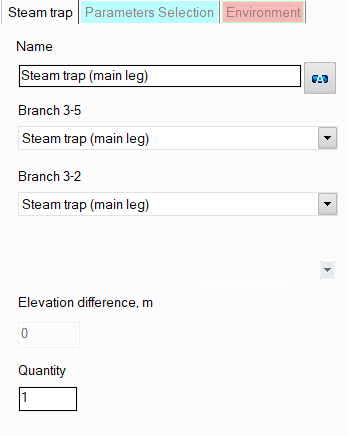
name - by default, all niches are assigned standard names "Steam trap (main leg)". However, if necessary, these names can be changed in this field. Specify the name that you would like to see for this element in reports with calculation results. To display the name of this leg on the diagram, click the corresponding button to the right of the name. If you need to enable displaying the name of another steam trap leg on the diagram, select the corresponding leg on the diagram or in the project tree and click the corresponding button to the right of the name in the Object Properties window for it;
steam trap leg type - currently not adjustable;
quantity - this parameter is usually not used for steam traps. It is used for other pipeline elements (for example, for valves) when modeling several identical elements. In this case, you can enter the number of these elements in this field and at the calculation the hydraulic resistance and heat losses on this element will be multiplied by the specified value. Since there are unlikely to be several identical steam traps in one pipeline branch, this option is of no practical interest for it.
Please note that from a hydraulic point of view, steam traps are considered as "point" (or "concentrated") resistances that have no lengths. Therefore, if it is necessary to take into account in the calculation the dimensions of the branching legs at the point where steam trap is located (to calculate and account for the friction losses, heat losses and hydrostatic pressure drop that occur on them), they can be modeled separately as pieces of pipes with the corresponding lengths, or their lengths can be added to the lengths of the pipes adjacent to the corresponding steam trap niches. However, this only makes sense in cases where:
these niches have really large sizes that cannot be neglected;
one or all of the niches of the steam trap are located in a vertical or inclined plane relative to the vertical - in this case, it is important to take into account the hydrostatic pressure differences that occur on them;
one or all of the niches are located in a closed loop (so that the piping model looks correctly, without gaps).
In other cases, losses in the steam trap niches (and therefore their lengths) are usually neglected.