Flow turn
To add
a new flow turn, click the button  of Components toolbar
or use the corresponding item of "Insert
- Component" menu. Please note that the new component
is added to the project tree after the currently selected element. Therefore,
to add a new component after an existing one, select it in the project
tree or in the graphic window and add the new component. If you need to
add a new component to the beginning of a branch, select the branch in
the project tree and add the new component.
of Components toolbar
or use the corresponding item of "Insert
- Component" menu. Please note that the new component
is added to the project tree after the currently selected element. Therefore,
to add a new component after an existing one, select it in the project
tree or in the graphic window and add the new component. If you need to
add a new component to the beginning of a branch, select the branch in
the project tree and add the new component.
The flow turn element
is used to simulate the resistance of the sharp flow turn (in contrast
to a bend, where usually the flow turns smoothly).
After
adding a flow turn, its characteristics will be displayed in the Object
Properties Window:
|
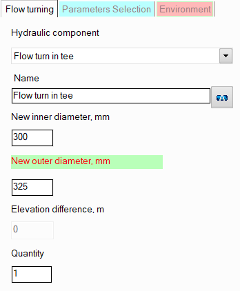
Flow
turn (with sharp edge on turn and without niche) |
Models
a sharp 90° flow turn. As additional parameters,
it is necessary to specify the diameter of its niche
after the turn, if it differs from the diameter before the turn
(the same diameter as before the turn is used by default). |
|
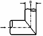
Flow
turn in tee (with one main niche closed) |
Models a
tee with a blocked flow along the main line. As
additional parameters, it is necessary to specify the
diameter of the tee niche after the turn, if it differs from the
diameter before the turn (the same diameter as before the turn
is used by default). |
|
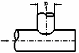
Z-type flow turn |
Models
the Z-shape turn - see the picture on the left. |
The specified values
of the new inner and outer diameters
of the flow turn niche after the turn are applied to
all components of
the branch after this component until
the end of the branch or until the next component with
a diameter change (if there is one in this branch). Please note that when
adding and deleting such flow turns
(with a change of diameter),
as well as when changing their new diameter value, the program will not
only automatically adjust the values of the diameters of all the following
components in this branch (up to the first element with a change in diameter
if any), but will also change the values of the radii of the bends
and elbows in this branch if they are equal to the standard value of 1.5*DN (for
pipes with DN < 500mm) or 1*DN (for pipes with DN >=
500mm).
name -
by default, the name of any piping component coincides with its type,
but if necessary, the name can be changed in this field. When changing
the hydraulic component type (when selecting different types of flow
turns), its name will also change, but only if it has not been previously
changed to another manually. Specify the name that you would like
to see for this element in reports with calculation results. To display
the name of a pipeline element on the diagram, click the corresponding
button to the right of its name;
quantity -
this parameter is used in cases when it is necessary to simulate and
calculate the resistance of several identical flow turns in a branch
without specifying each of them separately. To do this, you need to
specify the number of such flow turns in this field, and at the calculation,
the hydraulic resistance on this element will be multiplied by the
specified value. Of course, not all flow turns will be displayed on
the graphical diagram (only one of them will be displayed), but they
will be taken into account in the calculation. However,
it is important to note that this method of setting not always gives
a good accuracy of calculation, since it does not take into account
that a change in pressure and temperature after the next piping component
may entail a change in the density and viscosity of the fluid (which
is especially crucial for gases and gas-liquid mixtures), and, consequently,
a change in the pressure drop on subsequent elements. This method
can be used for a quick rough estimate and mainly for liquids, the
properties of which don't change (for instance, at a constant temperature)
or change slightly along the pipeline. For a more accurate calculation,
you should specify all components sequentially in the exact order
they appear (even if there are repeating ones among them).
Please
note that from a hydraulic point of view, a flow turn is considered as
a "point" (or "concentrated") resistance that has
no length. Therefore, if it is necessary to take into account the dimensions
of the flow turn niches in the calculation (to calculate and account for
the friction losses, heat losses and hydrostatic pressure drop that occur
on them), they can be modeled separately as pieces of pipes with the corresponding
lengths, or their lengths can be added to the lengths of the pipes adjacent
to the flow turn. However, this only makes sense in cases where:
the flow
turn niches have really large lengths that cannot be neglected;
one or both flow
turn niches are located in a vertical or inclined plane relative
to the vertical - in this case, it is important to take into account
the hydrostatic pressure drop that occurs on them;
the flow
turn is located in a closed loop (so that the piping model
looks correctly, without gaps).
In other cases, friction losses in
flow turn niches (and therefore their lengths) are usually neglected.
It is not recommended to install
flow turns as the first and last elements in a branch, since the orientation
of the flow turn in space is determined by the directions of the pipes
located before and after it. Therefore, if there are no pipes before and/or
after the flow turn, it will be impossible to accurately determine its
orientation in space, and the flow turn may be displayed incorrectly on
the diagram (however, of course, this will not affect the correctness
of the calculation).