
Learn more about PASS/START-PROF pipe stress analysis software
In stress analysis models, piping-to-equipment connections are often modeled as fixed anchors. This approach provides a conservative estimate for expansion stress calculations. However, it can significantly overestimate the loads transferred from piping to equipment. Accounting for actual connection flexibility substantially reduces these calculated loads.
The finite element method (FEM) provides the most accurate approach for determining nozzle flexibility. PASS/Nozzle-FEM calculates stresses and flexibility at nozzle-to-shell junctions using FEM. The software determines allowable nozzle loads and assesses junction strength for various geometries and operating conditions. It enhances equipment safety while reducing engineering time during design. Mechanical engineers and piping designers use PASS/Nozzle-FEM to verify compliance with pressure vessel nozzle load requirements and analyze non-standard fittings. The software is suitable for oil and gas, refinery, petrochemical, power, and other industrial applications. It also calculates stress intensification and flexibility factors for tees outside ASME B31 scope, including lateral tees and tees with D/T>100.
Unlike general-purpose FEM software, PASS/Nozzle-FEM requires no specialized training. It automatically generates meshes and evaluates results.
Approximate methods like WRC 297 and PD 5500 remain popular due to their accessibility and speed. However, these semi-analytical methods have limitations and lower accuracy compared to FEM. PASS/Nozzle-FEM provides an alternative when method limitations are exceeded.
Where:
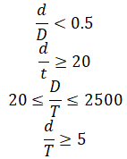
d - Nozzle outside diameter
t - Nozzle wall thickness
D - Vessel outside diameter
T - Vessel wall thickness
If any application limit is exceeded, the nozzle is treated as rigid.

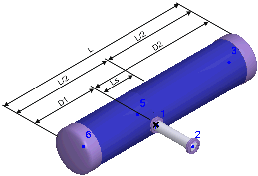
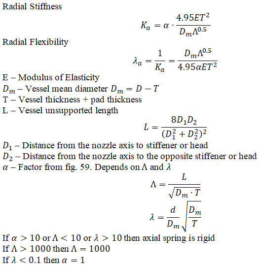
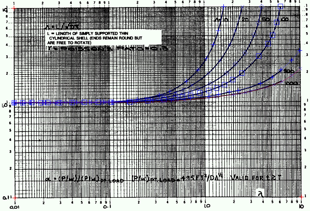
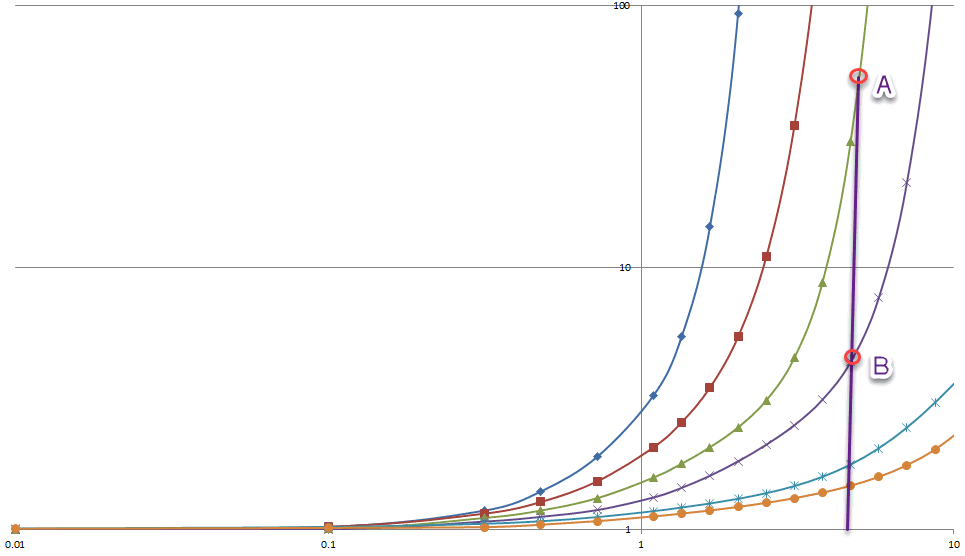
Figure 59 curves were approximated using 10th-degree polynomials and extrapolated to alpha values up to 10.0. PASS/START-PROF interpolates between curves for alpha ≤ 10. For alpha > 10, the program uses rigid axial springs.


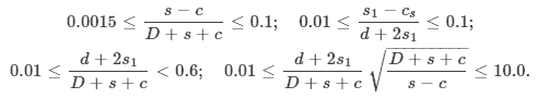
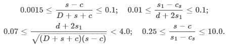
Nozzle internal sections are not included in flexibility analysis. Spherical shell and elliptical head nozzle junctions use identical models. The following limitations apply to nozzle junction stiffness analysis:
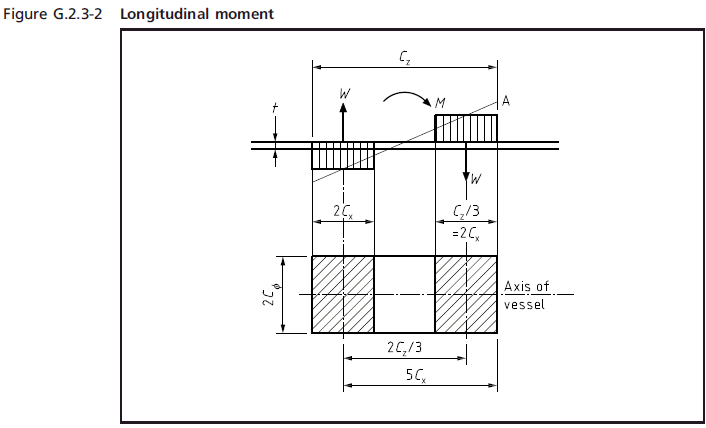
where s – vessel wall thickness, D – shell internal diameter, d – nozzle internal diameter, L – shell length, Ls – nozzle offset from shell mid-length.
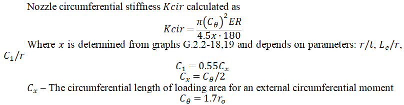
Nozzle-to-vessel junction flexibility (stiffness) is calculated in three directions:
 ;
; ;
; .
.The corresponding flexibilities are:

The remaining three degrees of freedom are considered rigid: (VL and VC linear directions, and MT torsion about the nozzle axis).


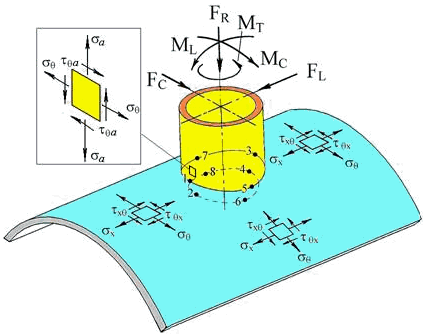
WRC 107/537 provides methods for calculating local stresses in cylindrical shells, spherical shells, and elliptical heads. However, it does not address nozzle wall stresses. This omission can lead to undetected overstress in thin-wall nozzles. WRC 537 presents the same methodology as WRC 107 but with digitized functions instead of graphs.
WRC 297 complements WRC 107/537 by providing nozzle wall stress evaluation methods, though it doesn't cover head calculations.
WRC 107/537 and WRC 297 should be used together as a comprehensive set. The Pressure Vessel Research Council (PVRC) recommends treating them as integrated documents. PVRC technical committees are developing additional publications to extend this methodology.
PASS/START-PROF implements a combined approach: WRC 537 for shell/head stresses and WRC 297 for nozzle stresses. This ensures complete coverage without omitting critical components. The software uses WRC 537 for cylindrical shells, spherical heads, and elliptical heads, plus WRC 297 for nozzle evaluation. This optimized combination handles all common scenarios while checking both nozzle and shell/head stresses.
For detailed stress calculation methodology using WRC 537(107)/297, see the PASS/Nozzle-FEM Manual.
Branch pipe-to-cylindrical shell junctions must meet the following strength criteria:
Branch pipe-to-dished head junctions must meet these strength criteria:

1. WRC 297: Local Stresses in Cylindrical Shells due to External Loadings on Nozzles – Supplement to WRC Bulletin No. 107
2. PD 5500:2018 Specification for Unfired Fusion Welded Pressure Vessels
3. WRC 107: Local Stresses in Spherical and Cylindrical Shells due to External Loadings
4. WRC 537: Precision Equations and Enhanced Diagrams for Local Stresses in Spherical and Cylindrical Shells due to External Loadings (WRC 107 Implementation)