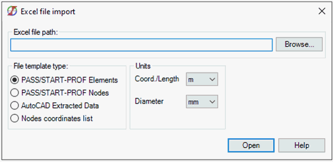
PASS/START-PROF imports pipeline geometry from Excel spreadsheets (.xls, .xlsx, .csv) using specialized templates.

Available import templates:
Transfers complete pipeline geometry including nodes, sections, and components.
Template file: Excel Import Example (START Elements).xlsx
Located in: Help > Example Models
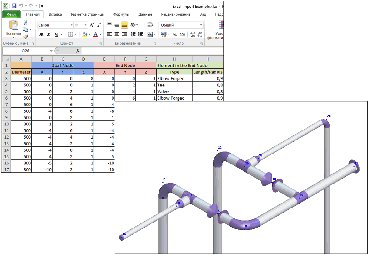
Each row defines a pipe section with:
- Outer diameter
- Start node coordinates
- End node coordinates
- End node component type
| Elbow Forged |
| Elbow Welded |
| Bend Miter |
| Bend Induction |
| Bend Long Radius |
| Bend Prestressed |
| Bend Miter Joint |
| Cap |
| Flange pair |
| Reducer con. |
| Tee |
| Valve |
| *empty* (creates node only) |
- Component parameter (length/radius)
| Elbow Forged radius |
| Elbow Welded radius |
| Bend Miter radius |
| Bend Induction radius |
| Bend Long Radius radius |
| Bend Prestressed radius |
| Bend Miter Joint radius |
| Cap *not set* |
| Flange pair length |
| Reducer con. length |
| Tee length |
| Valve length |
Sections with matching coordinates connect automatically.
Import steps:
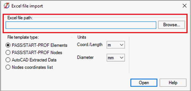
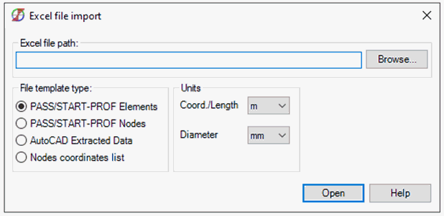
- Specify Excel file path:
- Select unit conversion:
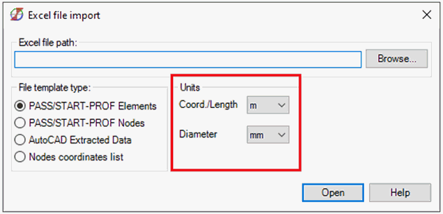
a) "Coord./Length" applies to:
b) "Diameter" applies to:
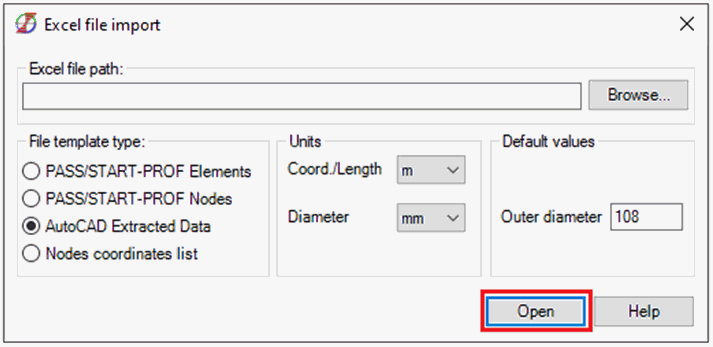
- Click "Open"
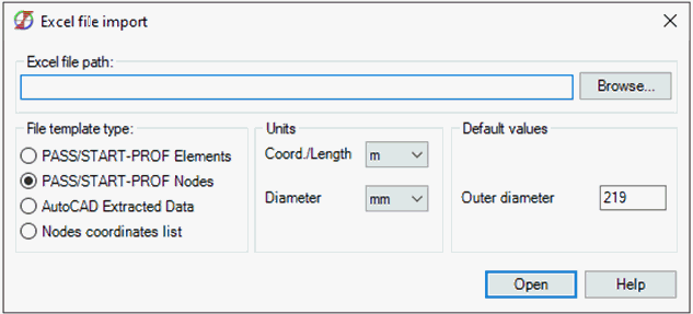
Transfers nodes, sections, bends, restraints, movements, and soil parameters.
Template file: Excel Import Example (START Nodes).xlsx
Located in: Help > Example Models
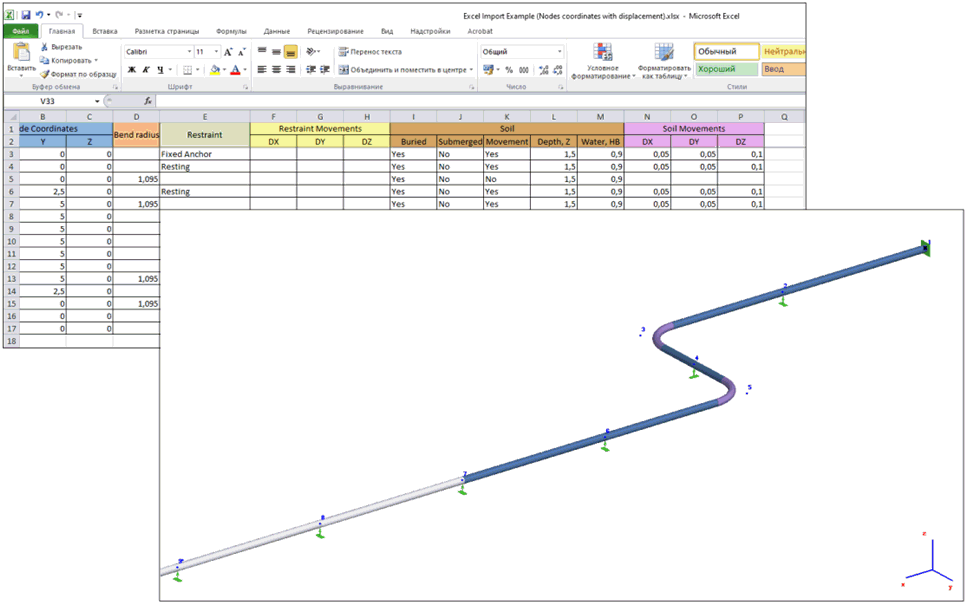
Each row defines a node with:
- Node coordinates
- Bend radius (creates Long Radius Induction Bend)
- Restraint type (mutually exclusive with bend radius)
| Fixed Anchor | Fixed Anchor |
| Moment Free Anchor | Moment Free Anchor |
| Resting | Resting support |
| Guide Single | Single-direction Guide |
| Guide Double | Double-acting Guide |
- Restraint movement
- Buried pipe flag
- Submerged pipe flag
- Soil movements consideration
- Depth to insulation top
- Water level from pipe axis
- Soil movement values
- Node name
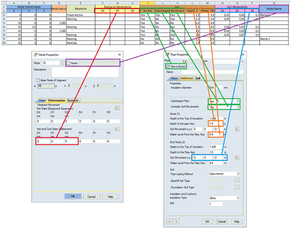
Import steps:
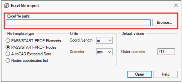
- Specify Excel file path:
- Select unit conversion:
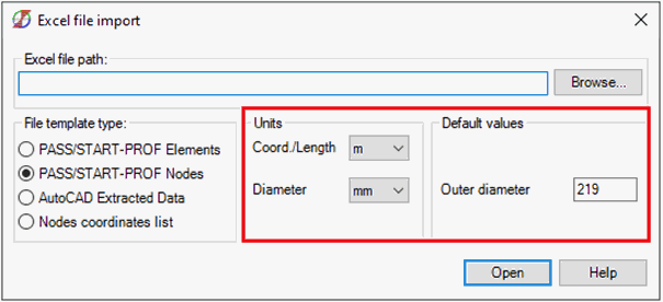
a) "Coord./Length" applies to:
b) "Diameter" applies to:
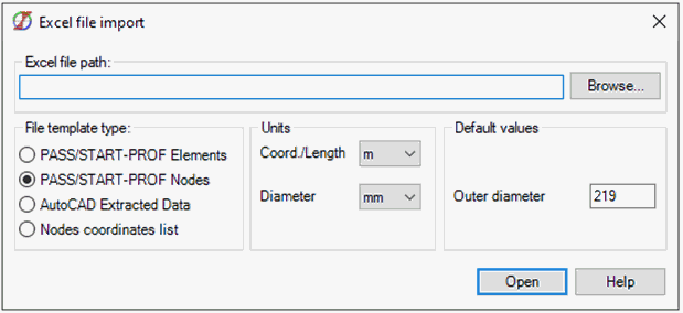
- Click "Open"
Imports pipeline geometry from AutoCAD drawing data extraction.
Template files: Excel Import Example (AutoCAD).dwg and Excel Import Example (AutoCAD).xls
Located in: Help > Example Models
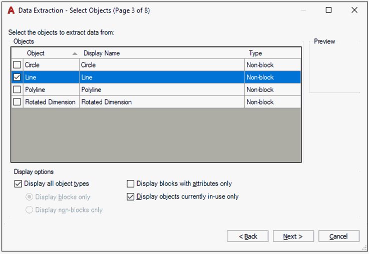
Convert polylines to lines before extraction. Use: Annotate tab > Tables panel > Extract Data
Select line geometry with start/end point properties:

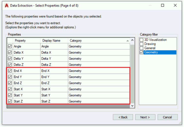
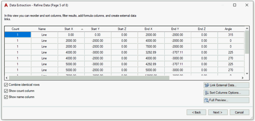

Import steps:
- Specify Excel file path:
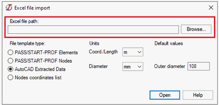
- Select unit conversion and set pipe OD:
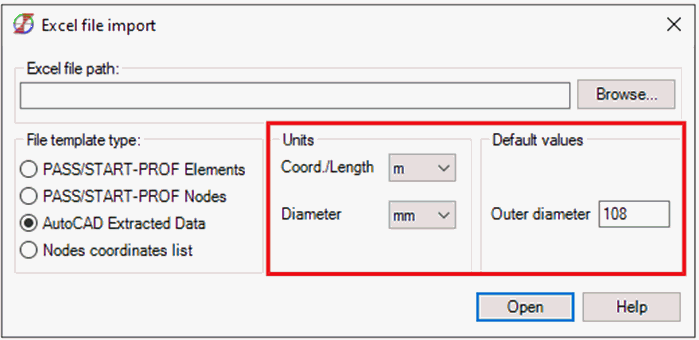
a) "Coord./Length" applies to coordinate columns:
b) "Diameter" applies to Outer Diameter field
- Click "Open"
Imports pipeline geometry from simple node coordinate lists.
Template file: Excel Import Example (Nodes coordinates list).xls
Located in: Help > Example Models
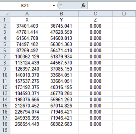
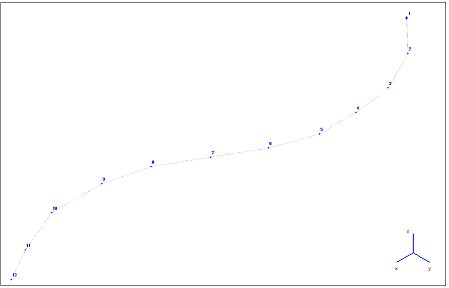
The import detects columns labeled "X", "Y", "Z" and processes data below the header.
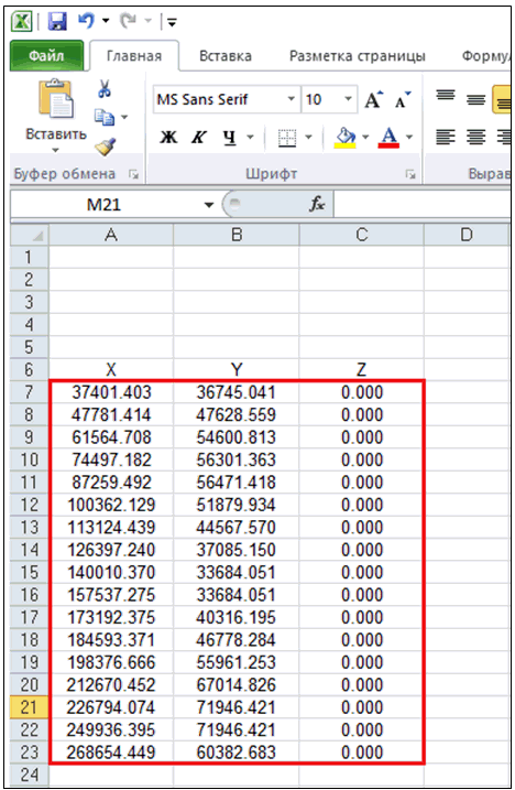
Rows 1-6 ignored, 7-23 converted to nodes
Without standard headers, all rows convert to nodes (some with zero coordinates):
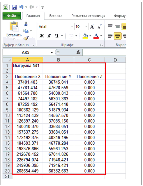
20 nodes created instead of 17
Import steps:
- Specify Excel file path:
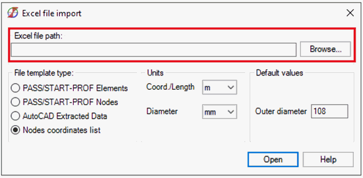
- Select unit conversion and set pipe OD:
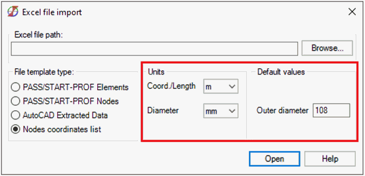
a) "Coord./Length" applies to X, Y, Z columns
b) "Diameter" applies to Outer Diameter field
- Click "Open"
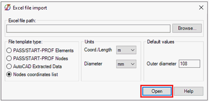
File > Import > From Excel
File > Open > Excel Format (*.xlsx, *.xls, *.csv)