

Learn about PASS/START-PROF pipe stress analysis software
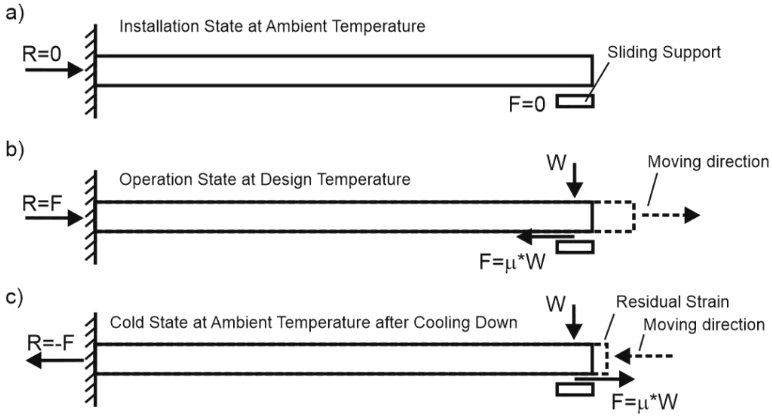
Consider a simple cantilever pipe model with a fixed anchor at the left end and a sliding support at the free right end.

During installation (a) at ambient temperature, friction forces are zero due to no displacement. The fixed anchor load R equals zero.
During operation (b), thermal expansion causes the right end to slide rightward. Friction opposes movement, creating a leftward force F = µ×W, where W is the support weight load and µ is the friction coefficient. The fixed anchor load becomes R = F.
Do friction forces and support load R persist in the cold condition (c)? Yes. During cooldown, the pipe end slides leftward, reversing friction direction to the right. At ambient temperature, friction forces remain, resulting in a fixed anchor load R = -F. This creates a cold spring effect, leaving the pipe in tension with non-zero support loads.
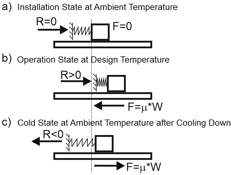
This behavior resembles a spring and brick analogy. Pushing the brick right (b) then pulling it left (c) leaves the spring stretched with a non-zero reaction force R.
Pipe stress analysis must account for this effect.
Standard analysis often assumes zero cold-state friction. Typical load cases include:
L1: W+P SUS (Sustained)
L2: W+P+T OPE (Operating)
L3: L2-T COLD (Follow-up from L2)
L4: L2-L1 EXP (Expansion range)
L5: L2-L3 EXP (Expansion range)
Expansion stress range L4 compares operating (L2) and installation (L1) conditions. However, range L5 between operating (L2) and cold (L3) conditions may differ.
Operating condition L2 produces compressive stress S = -F/A.
Installation condition L1 produces zero stress S = 0.
Cold condition L3 produces tensile stress S = +F/A.
Thus, L4 expansion range yields SA = | -F/A | = F/A, while L5 yields SA = | -F/A + F/A | = 2F/A.
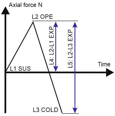
Range L5 is twice that of L4. Calculating expansion range between operating and cold states (L2-L3) with friction is more accurate than between operating and installation states without friction (L2-L1).
Friction coefficients decrease after initial movement. For L5 stress range calculations, reduce the friction coefficient by half. For example, if µ = 0.3 for L2, use µ = 0.15 for L3, giving SA = | -F + 0.5F | / A = 1.5F/A.
To analyze this in PASS/START-PROF, create a model with a fixed anchor at one end and a sliding support with a heavy valve at the other.

Cold state friction analysis is a standard feature in the operation mode editor.
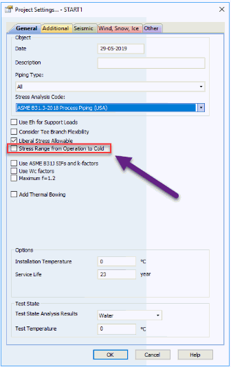
With "Stress Range from Operation to Cold" disabled, PASS/START-PROF calculates range L4 (operating to installation). When enabled, it calculates range L5 (operating to cold) including reverse friction effects.
Stress tables show range L5 is twice that of L4.
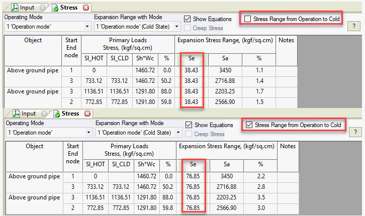
Compare support loads: X-direction load is zero in installation (L1) but equals friction force in cold state (L3). Cold state nozzle loads may exceed hot state values in some cases.

Multiple heating/cooling cycles produce slightly different displacements each cycle.
For multiple thermal cycles:
L1: W+P SUS
L2: W+P+T OPE
L3: L2-T COLD (Follow-up from L2)
L4: L3+T OPE (Follow-up from L3)
L5: L2-T COLD (Follow-up from L4)
L6: L3+T OPE (Follow-up from L5)
L7: L2-T COLD (Follow-up from L6)
L8: L3+T OPE (Follow-up from L7)
...
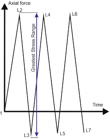
For L-shaped piping, sliding support displacements in the XY plane appear as:
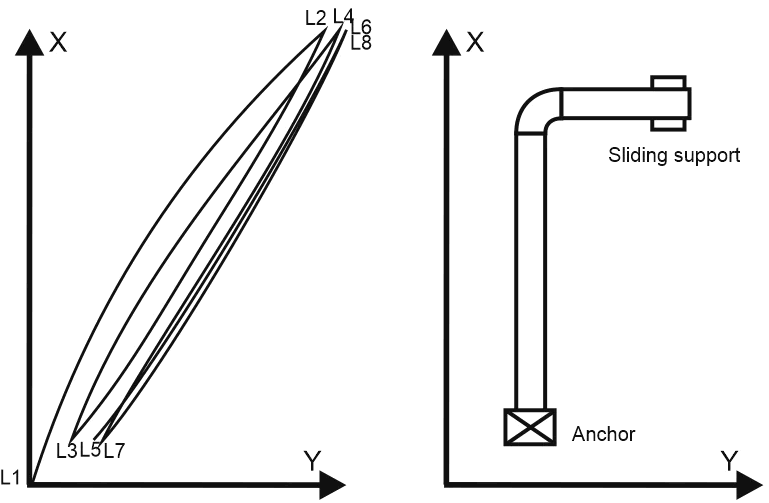
Peak loads occur during the first cycle L2-L3. The L2-L3 stress range exceeds L1-L2.