

|
PASS/NOZZLE-FEM 3.6. Program Manual | |
Table 3.13 shows key features of the base element (shell).
| Table 3.13 | |
 | |
| Feature | Description |
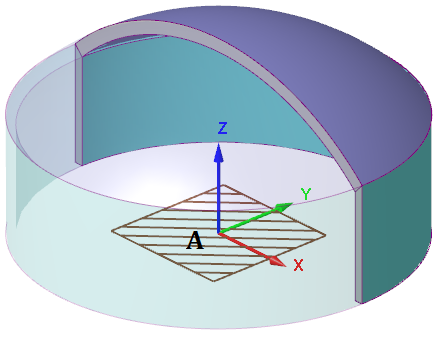
| Reference points: | A: head (cylindrical part) bottom. |
| Local shell coordinate system (LCS): | Axis X: transverse axis in head plane; Axis Y: transverse axis in head plane; angle θ of nozzle insertion is taken from this axis toward axis X; Axis Z: normal axis to head plane. |
| Orientation in WCS: | All axis can be horizontal and vertical according to the shell options: 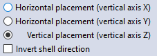 Additionally, can flip the element relative to its plane to simulate the head of the pressure vessel. |
| Shell constraints (dof): | Point A. Point A is free in stress analysis in the presence of support legs. All calculations by the finite element method (FEM) fix bottom end of head. If cylindrical part is set then its bottom part is fixed. |
| Shell loads: | Inner overpressure. Outer pressure. Hydrostatic pressure. Different temperatures for the head and its cylindrical part. Thermal strains. |

PASS/NOZZLE-FEM 3.6. Program Manual
Copyright © 2017-2026, PASS Team