

|
PASS/NOZZLE-FEM 3.5. Program Manual | |
Table 3.7 shows key features of the base element (shell).
| Table 3.7 | |
 | |
| Feature | Description |
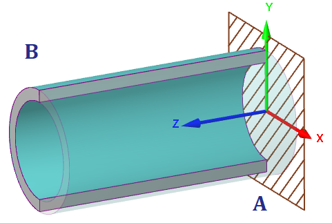
| Reference points: | A: shell start; B: shell end; |
| Local shell coordinate system (LCS): | Axis X: shell transverse axis; Axis Y: shell transverse axis; angle θ of nozzle insertion is taken from this axis toward axis X; Axis Z: shell longitudinal axis. |
| Orientation in WCS: | Axis Z is located in horizontal plane. Axis X and Y can be vertical according to the shell options: 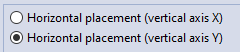 |
| Shell constraints (dof): | For strength analysis (fig. 3.29): Point A. The boundary conditions of the header second end relate from option state when calculating allowable loads, stiffnesses and stress intensification factors for a nozzle:  Point A: option disabled (fig. 3.29). Points A, B: option enabled (fig. 3.30), default. 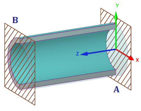 |
| Shell loads: | Inner overpressure. Outer pressure. Hydrostatic pressure. Thermal strains. Concentrated loads to free end (B) for strength analysis (fig. 3.31): 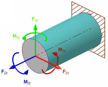 |
| Special calculations: | Allowable loads for runhead pipe (fig. 3.32). Stiffness and flexibility factors for runhead pipe (fig. 3.32). Stress intensification factors (fig. 3.32). 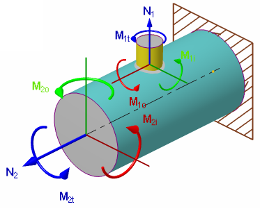 |
| Additional segments: | The base element allows to add cylindrical segments at the start and end. 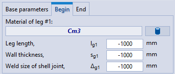 If the cylindrical segment length $l_{g1}$ ($l_{g2}$) is set to a negative or zero value (default), then the corresponding segment will not be added. If the remaining values are set to negative values, they will be accepted as for the main part. When is added the segment, the restriction on the distance from this edge to the fitting decreases by $\sqrt{0.3 D s}$. |
PASS/NOZZLE-FEM 3.5. Program Manual
Copyright © 2017-2026, PASS Team